Soldering modern surface mount chips, such as QFPs, SOICs, and TSSOPs, is much easier than it looks. This tutorial will have you soldering with confidence in no time.
Today’s components are built in tiny packages with even tinier pins. Many useful chips are only available with pin spacings of 0.5 mm or less. The reaction of people used to soldering old-style through-hole parts is often, “how on earth am I supposed to connect those tiny pins without solder bridges?” I’ve even seen a company produce boards in which every pin of a TSSOP was hand-soldered under a microcope using fine solder and the smallest soldering iron tip available. That worked for the mom-and-pop company that was doing it, but it won’t work for me.
The key to soldering these chips easily is the “lake of solder”. With this technique, a whole row of pins are bathed in an excess of solder, without any concern for bridges.The excess solder is then removed with solder wick, leaving only the solder between the pin and the circuit board. The result is an accurately soldered chip with minimal effort.
1. Materials
The lake of solder method requires some materials beyond the usual for through-hole work.
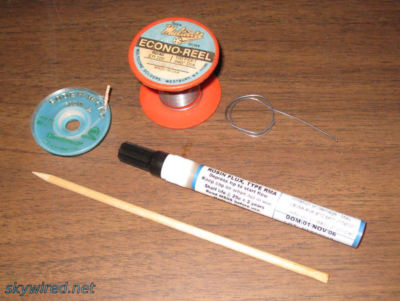
Critical for the process is unsoldering wick. I like the Solder-Wick brand, but any decent quality wick will work. (Watch out for off-brands. A hamfest special I once bought had no absorptive powers and was completely useless.) Also critical is a flux pen or another way to put liquid flux where you want it.
You will need solder, of course. I think an 0.040″ solder like this one works well for the job, but anything should work.
I find it very helpful to have a tool to help me nudge the chip into place. My favorite is the “orange stick” in the picture. It came in a package of trimming tools. It is simply a piece of wood with a point at one end and flattened like a screwdriver at the other. Anything similar will work fine.
Beyond that, a soldering iron is essential, and a magnifier will be helpful.
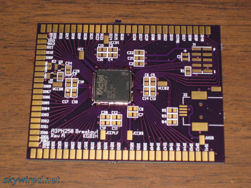
Here are the guests of honor for the event:
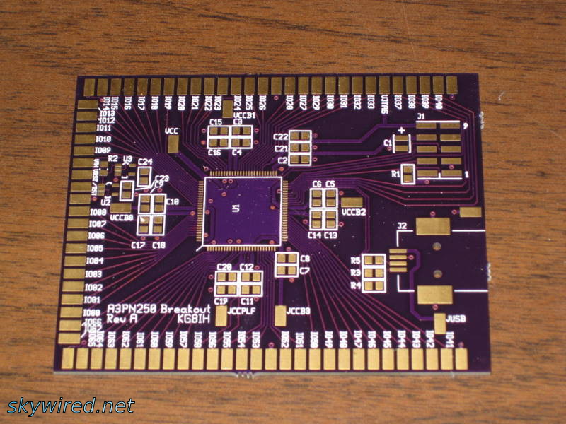
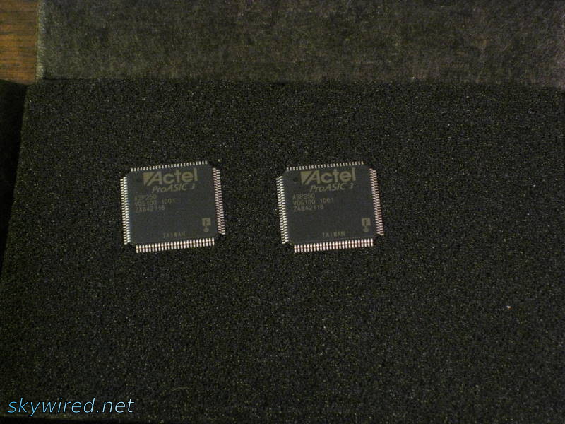
The printed circuit board for this assembly is the FPGA Breakout Board described elsewhere on Skywired. The chip is an Actel (now part of Microsemi) FPGA, part number A3PN250. It is 14 mm wide (slightly more than half an inch) and has 100 pins spaced 0.5 mm apart. I can’t imagine trying to solder it with the pin-at-a-time techniques of through-hole assembly.
2. Alignment
The first step of the process is to put the chip on the board and move it until all of its pins are aligned with all of the pads. I find that it helps to use a finger and a nudging stick on opposite corners. My finger provides even pressure against which the nudging stick works to carefully push the chip in place. A magnifier helps, too.
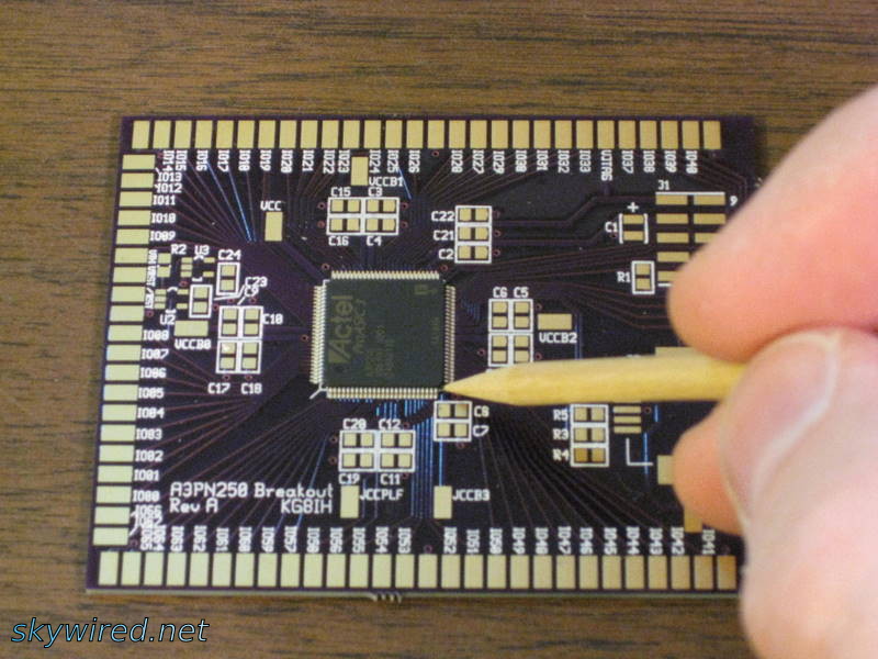
As you move the chip around, you may notice an odd flashing effect when the pins line up with the pads. When they are misaligned, the pins and the pads are both shiny and reflect the light back, but when they match up, the darker board material is visible. On a fine pitch part like this, the effect can be sudden. Take advantage of the effect and look for darkness between the pins on all four sides of the chip at the same time.
Take care to only nudge the chip horizontally, and use the chip body, not the pins, to move the chip. Fine-pitch pins are delicate, and it is important not to bend them.
This is the most time-consuming step of the process. Be patient, and move the chip slowly and smoothly.
3. Tack the Corners
Once the chip is lined up, carefully tack down one pin in each of two corners to secure it on the board.
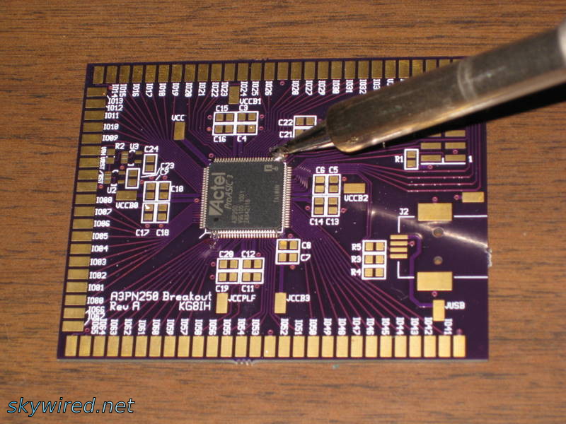
If your board has the inexpensive and popular hot air solder leveled (HASL or HAL) finish, you’re in luck. The thin coat of solder on the board is enough to hold the chip down. Just use the iron to heat it up enough to get a bond. The quality of the joint is not important. It only has to be enough to keep you from bumping the chip out of place as you solder the rest of it.
If the board has a different finish, such as gold plating or no finish, such as for do-it-yourself etching, it may not be possible to form a bond without adding solder. I added a bit too much on the chip in the picture. Next time, I will use a smaller diameter solder for better control.
4. Check alignment again
It’s time to check whether the pins are all squarely on the right pads one last time. From here on out, it’s going to be more difficult to correct an alignment problem.
Here is an example of the kind of problem to look for:
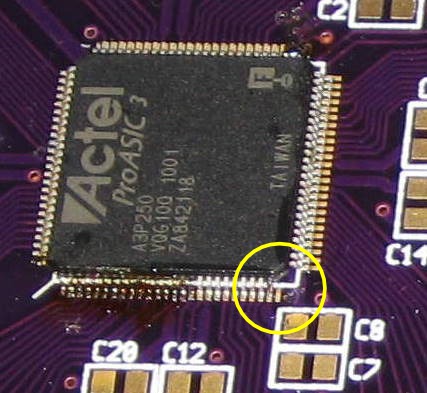
- This chip is rotated enough to be off by one pin on the bottom side. Unfortunately, it’s also partially soldered.
This chip rotated a bit during soldering and ended up off by one pin on the bottom side. That means that all four sides are wrong. There aren’t any easy ways to fix this problem with just a soldering iron. One solution is to cut all the pins, throw away the chip, and clean up the remaining pin detritus from the board. If the chip is too expensive for that, a hot air soldering system or its less refined cousin, a heat gun, may be able to unsolder the QFP without excessive damage to the chip or board.
In any event, this is your best opportunity to fix a problem with the chip’s positioning, so take your time and inspect it carefully, preferably under a magnifier.
5. Apply flux
Once you are sure the chip is still in the right place, prepare it for solder by adding some flux. Since you will be applying solder from the soldering iron tip, you can not count on the rosin core to supply the flux. I like to use a flux pen, though brushing on liquid flux would work, too.
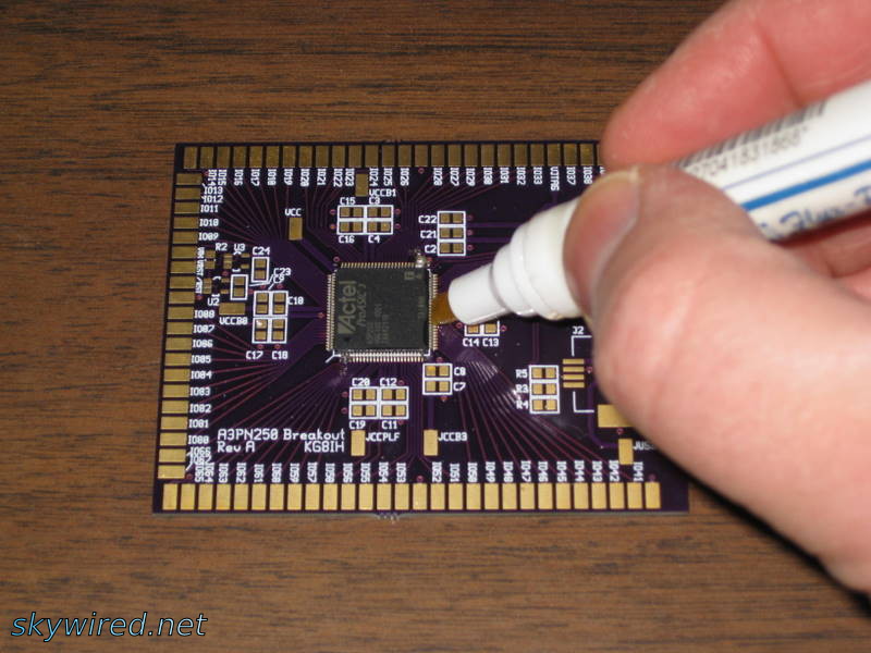
Be careful to use as little pressure as you can on the cantilevered part of the pins. After the care that went into aligning the chip, it would be a shame to bend a pin.
6. Make the lake of solder
Now we get to the fun part! The technique for applying solder breaks many rules I learned about soldering through-hole parts: “Don’t use the iron to carry solder to the joint.” “Watch out for cold joints.” “Be careful not to make bridges.”
To make the lake of solder, first melt some solder directly onto the tip of the iron. It helps to have a screwdriver tip on the iron, or better, a tip with a concave surface, but a conical tip works almost as well. Build up as much solder as you think it will take to go across all the pins on one side of the tip. Next, drag that blob of solder down one side of the chip. Let the solder flow over the whole of each joint you need to make, and don’t worry about solder bridges. The idea is to get molten solder all around the joint, so some of it will wick between the pin and the PCB.
Carrying solder to the joint on the iron is usually a bad idea because it doesn’t provide flux, but the flux applied in the last step makes up for it.
Take care which corner you start with when applying the solder. It’s a good idea to start with pins other than the ones you tacked earlier. Otherwise, when the tacked solder melts, the chip is free to pivot on the other pin. That can cause bent pins or a misaligned, soldered-down chip. If you start with an un-tacked pin, the bond you are making with the lake of solder will hold the chip once you get to the tacked-down pins.
7. Remove the excess solder
Once you have checked the pins to make sure that the joint area of every one is covered with solder, get out the solder wick. Place the wick to cover the pins on one side of the chip, then slowly drag the iron down the wick to absorb the excess solder. With a little practice, you will see the solder wick change color slightly as it gets hot enough to start absorbing solder, then you will see a shiny silver color emerge around the iron tip as solder from the PCB flows all the way through the solder wick. That’s usually the signal that it is time to move the iron tip down a little bit and get the next few pins.
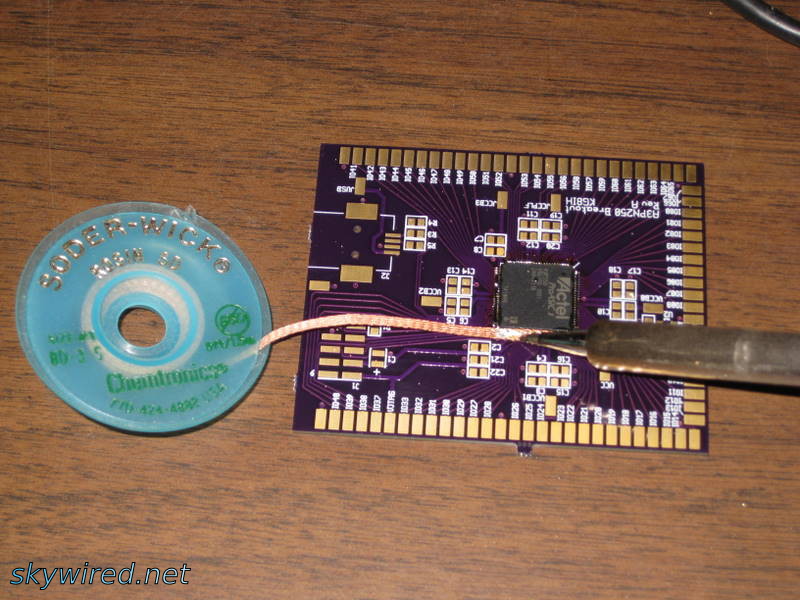
Once the wick has absorbed the solder from the whole side of the chip, remove it and check your work. The wick may have firmly soldered itself to the PCB as it cooled. If that happens, just heat it up with the iron and pull it off as it becomes loose. Using force to remove it could bend pins and lift pads off the PCB.
Once each side of the chip is done, move on to the next one.
8. Inspect the joints
With the excess solder gone from all of the pins, it is time to carefully inspect your work. If you have a magnifier, use it. You should see shiny solder joints on every pin and pad, and you may be able to see tiny fillets on the sides of each pin. Watch out for these problems:
- If solder is missing from some pins or pads, apply flux and solder to those pins, then use a little more solder wick to clean them up.
- If you see solder bridges, use solder wick to remove the excess solder.
- This is a good time to check for short-circuits between pins by walking down them with a pair of probes and a multimeter set to continuity-tester mode. If the pins are really tiny, dental picks (or the electronics equivalent) work well as probes. Use alligator clips to connect the probes to the meter.
Once you find your handiwork satisfactory, sit back and admire your work. You have done it. You have soldered numerous pins too tiny to solder individually.
After a few minutes, though, you will start to see the ugly side of your success: a mess of flux residue all over the chip and PCB.
9. Clean up
All fluxes are corrosive, even no-clean fluxes, and flux residue provides a sneak path for currents that can bedevil high-impedance or low-leakage circuits. Clean that flux! Isopropyl alcohol (IPA) and a little scrubbing works for most fluxes, or you can use a purpose-made flux cleaner.
Once the flux has dissolved into the liquid, make sure you flush it away. You can use more solvent or distilled or deionized water. The key is to make sure the flux is washed away, not redeposited on the board as the IPA or flux remover evaporates.
Closing thoughts
Once all your sub-millimeter pitch chips are soldered, sit back and open your favorite beverage. (This might be a good time to enjoy the other kind of IPA.)
There are other ways to solder QFPs, MSOPs, TSSOPs, and similar tiny parts. Reflow techniques are popular and very time-efficient, though they require special equipment and some experience for success. SparkFun has a whole series on surface-mount assembly, including soldering with a skillet and using solder paste and a stencil.
Thanks for reading this soldering tutorial. Please check out Skywired for more electronics, DSP, and ham radio content.
Sounds to me like there is potential here for a business idea/new product -essentially a carrier board that is easily soldered into place…
Hi, Nick. The thought has crossed my mind. There’s a strong market for SMT-to-throughhole adapters, but I haven’t found anything suitable for groundplane “dead bug” construction.
I suggest double fluxing. Flux the pads before placing the chip and then flux on top of the pins before soldering. If you just flux the top pins then very little works its way between the pin and pad which is where you want it in the first place!
When I solder TSSOPs or TQFPs, I use a “swipe soldering” method. I attach the part by a couple of corners and ensure alignment, soak it in flux, then tin the soldering iron and swipe the tip across each side of the device, re-tinning it as it runs dry. The surface tension of the solder “drags” it along to un-soldered pads, leaving nice joints on each pad. It requires a lot less work with the solder wick when finished.
I had similar experience and always prefer to use the flux pen when I do SMD soldering. It is a lot easier to flux the pins that way. Thank you for sharing this excellent surface mount soldering tutorial!