Replacing the BITX 40 BFO

The BITX 40 is all about modifications. The design itself is “cheap and cheerful”, and the circuit board is laid out to invite changes and experiments. I have a list of quirks I intend to fix in mine, and with that the mods began.

First up was a misalignment of the BFO. Each BITX 40 uses a set of 5 matched crystals, four for the IF filter and the fifth for the BFO. The BFO is set up to pull the crystal frequency slightly to put the audio passband in the right place, or at least it is supposed to. On mine, the BFO frequency was just inside the IF passband.

Having the BFO in the wrong place had several consequences. First, receive audio was bassy, running from about 0 Hz to 1800 Hz. This transmits audio frequencies that are not useful for communications and omits the ones around 2 kHz that are especially important. Worse, the passband actually stretch below 0 Hz, into the upper sideband, which meant that my transmitter was not suppressing the carrier. It was sending VSB, vestigial sideband, not SSB. That may be fine if you’re a TV transmitter, but it’s not the kind of clean SSB signal hams expect.

One solution, which Wayne NB6M used on his BITX 40, is to change the “pulling” capacitor in the BFO to put the frequency where it belongs. Instead, I replaced the BFO entirely with a spare channel on the Si5351 frequency synthesizer.

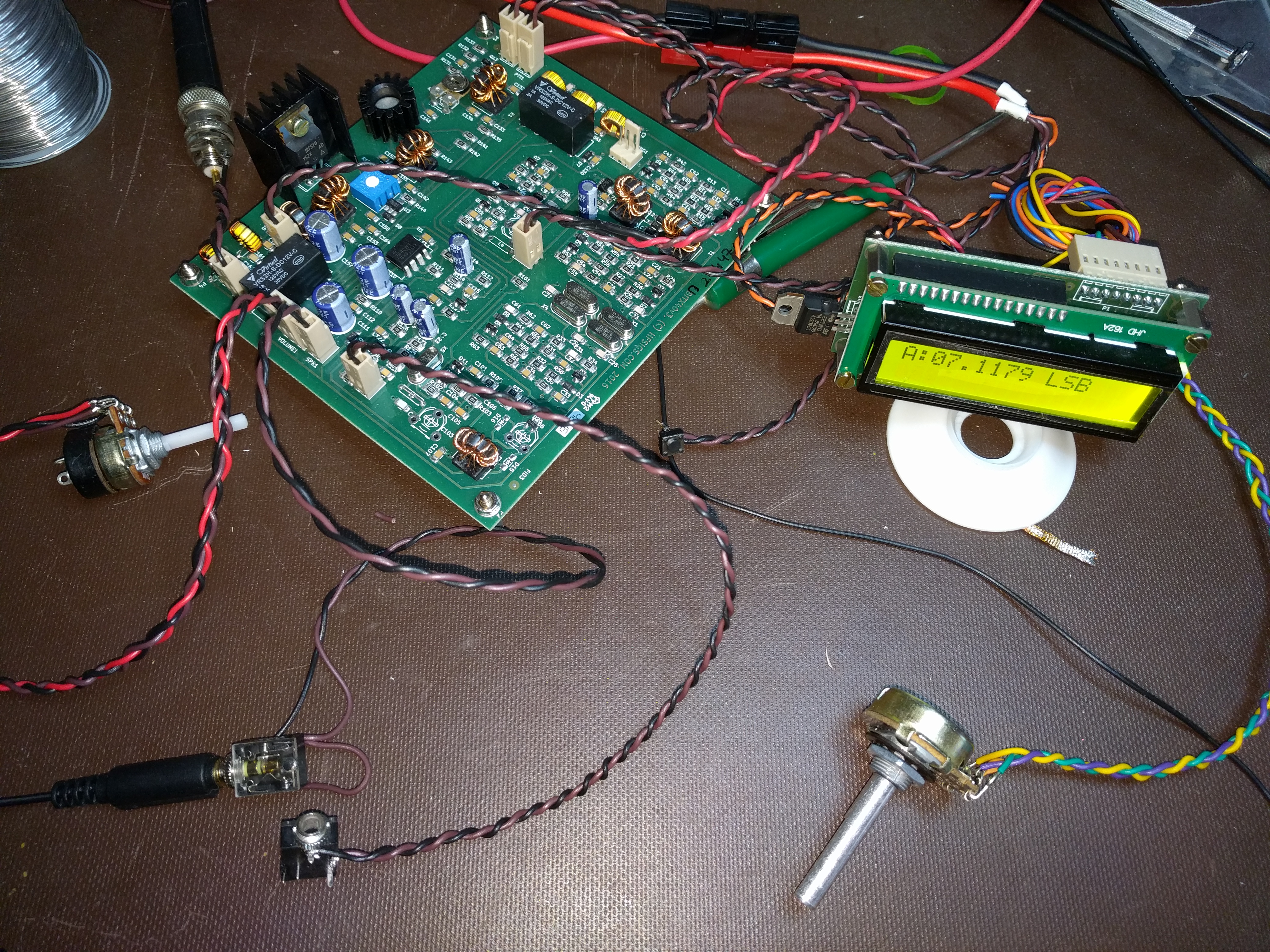
I started off by attaching wires to pins 8 and 9 of the Raduino board. These are Si5351 channel 0 and ground, respectively. For quick progress, I used a twisted pair. When I box it up, I will switch to coax and use a connector to make maintenance easier.

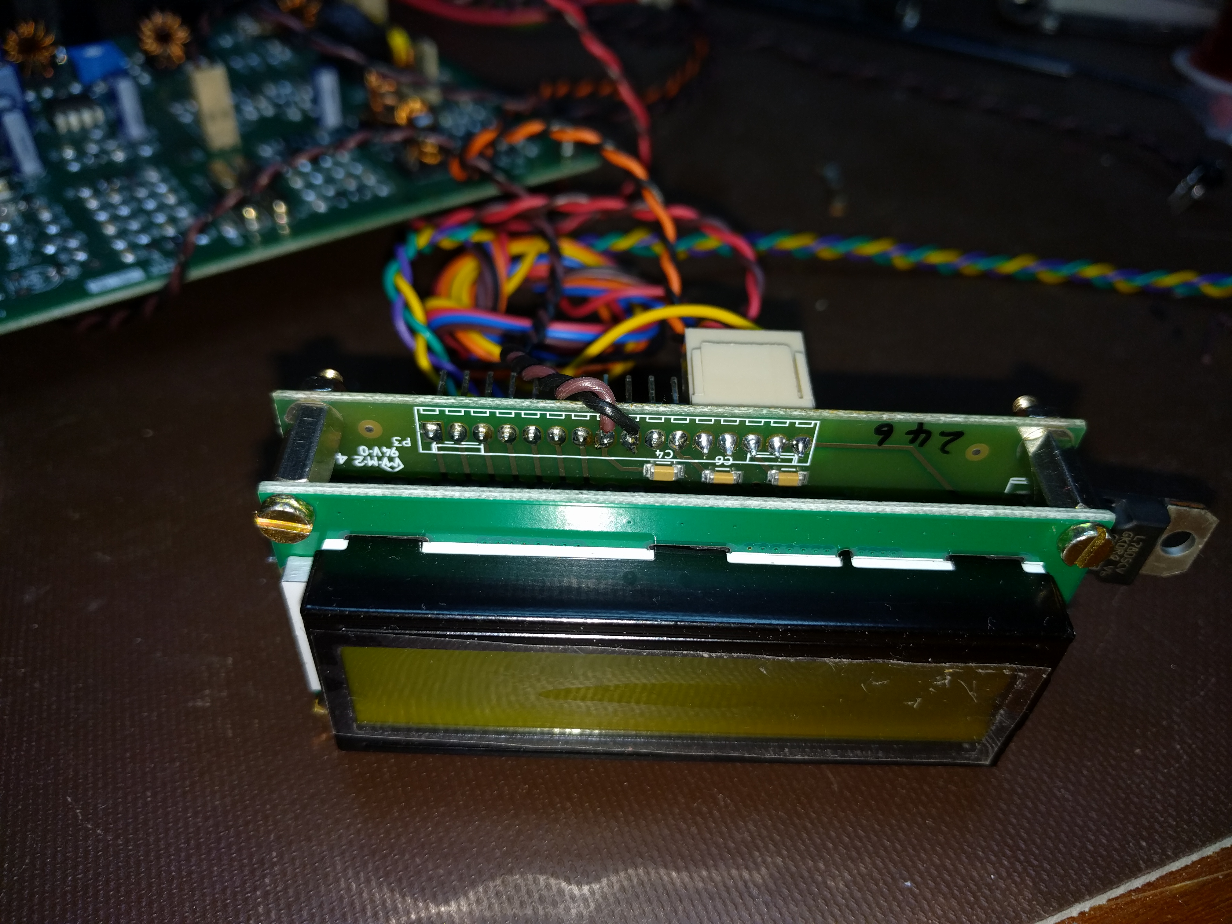
At the other end, I attached the wires to pins 1 and 6 of T4. This supplies the BFO to the second mixer.

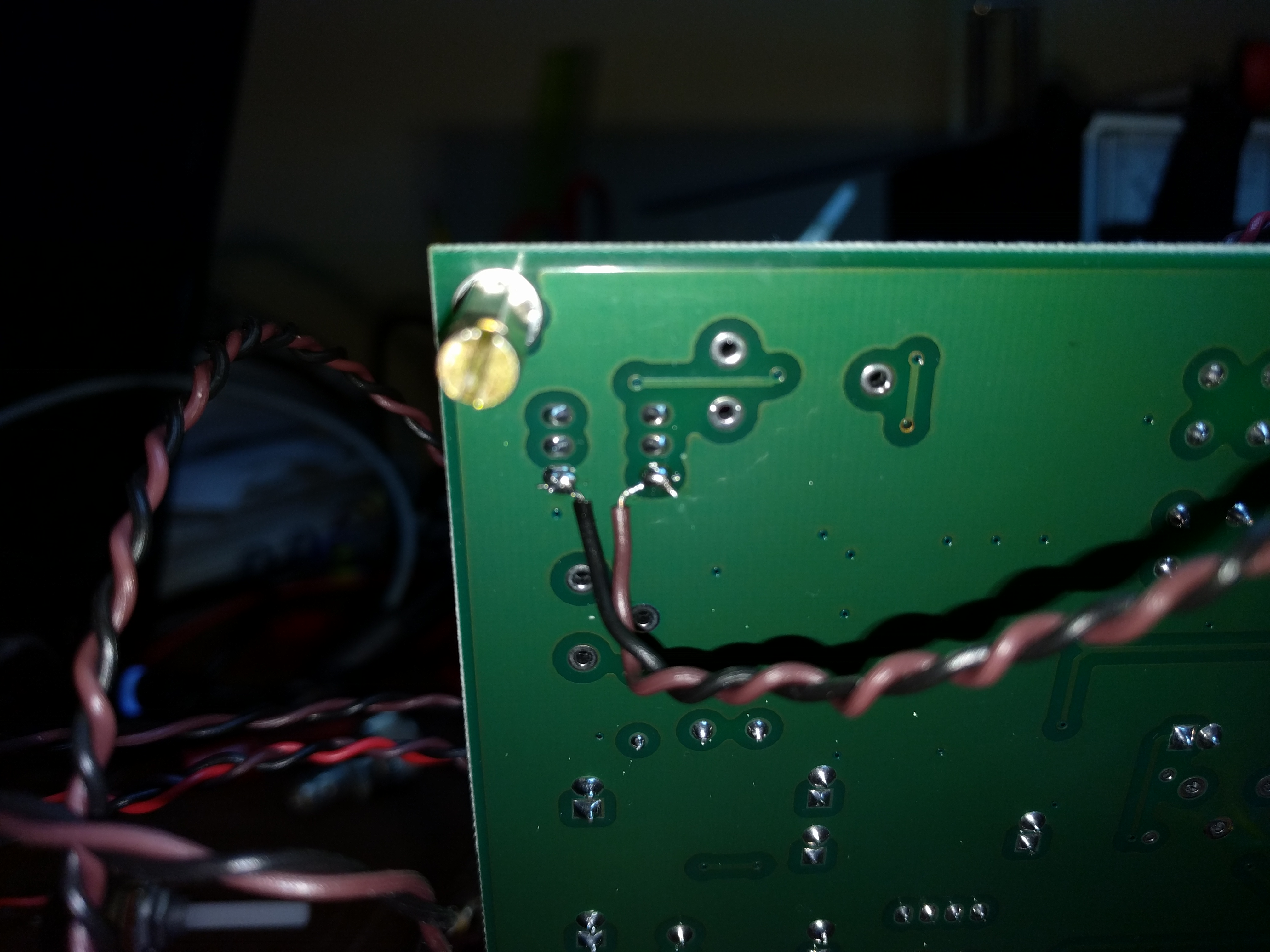
Finally, I unsoldered R101 and C106 to remove power from the analog BFO and disconnect it from the second mixer.

With the hardware work done, I turned to the Arduino code. I downloaded Ashhar Farhan’s original bitx40 sketch and added one line of code near the bottom of setup().

si5351.set_freq(bfo_freq * 100ULL, SI5351_CLK0);

Then I turned it on, saw that the BFO was now too far above the IF passband, and with a couple of experiments, came up with the following edit near the top of the sketch:

#define INIT_BFO_FREQ (11997000L)
unsigned long baseTune = 7100000L;
unsigned long bfo_freq = INIT_BFO_FREQ;

With that, I was done. The rig sounds better and works better. I still haven’t transmitted, though. That will take one more mod which I will write about next.

BITX 40!

I’ve decided to build a BITX 40. This petite SSB transceiver sells for a mere $59, some assembly required. As it comes, it puts out approx. 7W, and with some straightforward upgrades it can produce 25W. It comes as a fully-assembled PCB plus most of the parts needed to hook it up. A case, speaker, and a few other incidentals are not included. The board and radio are designed to invite hacking and customization. It is also designed to serve as an introduction to homebrewing for hams who may not be ready to build a radio from scratch. For more information on the BITX-40, see its supplier http://www.hfsigs.com/ and the active and helpful support community at groups.io.

My BITX 40 is operable “al fresco” on my workbench. The included Arduino/Si5351 VFO works fine and tunes the full 40m band. It needs a little bit of work before I can transmit with it. It’s important to understand that the BITX 40 is not a turnkey rig. Many of them ship with small flaws, and figuring out and fixing the flaws is part of the fun. (This is why that helpful community at groups.io is so important.) Mine shares a flaw with Wayne, N6BM’s BITX 40 — the BFO frequency is inside the IF passband, instead of about 300 Hz below the passband like it should. This means that stations I tune sound bassy, I can hear part of the opposite sideband, and when I transmit, the carrier is not suppressed.

(I suppose I could call it “vestigial sideband”, like what NTSC TV uses, but it’s supposed to be SSB…)

Wayne fixed the problem by changing a capacitor in the BFO circuit to pull the frequency where it needed to be. I plan to fix it by disabling the analog BFO and instead use a spare Si5351 output. Having a tunable VFO will let me put the passband exactly where I want. With a little more code, it will also give me passband tuning.

I think I found a bug in the microphone amp that I’m going to take a closer look at, and I found a perfect case at the Mike and Key hamfest in Puyallup last month. I didn’t even try to negotiate the price. It was free!

I’ll have more on my BITX 40 project in upcoming posts.

An Si570 VFO for the R2/T2 transceiver project

I’m continuing to work on my R2/T2 transceiver project as time allows. My goal is to get on the air before the sunspot cycle peak passes. That gives me a little time yet, but at the rate I get things built around here, it’s going to be a close race.

Even when building a radio from kits, as I am here, there are many decisions to be made. When I bought the KK7B R2 and T2 kits, I had no thoughts about what to use for a local oscillator. Technology has advanced mightily since then, and now I have the option of an Si570 frequency synthesizer. This little chip provides a precise, low-noise  digital clock at programmable frequencies between 3.5 MHz and 1.4 GHz, depending on the variant one buys.

After looking around a bit, I picked John Fisher K5JHF and Kees Talen K5BCQ’s SI570 controller/frequency generator kit. Once it arrived, I had trouble figuring out how to fit it into my case. This case has a 0.125″ thick aluminum front panel. The threaded bushing on the kit’s encoder/switch was not long enough for this thick panel and a mounting nut, let alone a washer. There were also some mechanical things I didn’t like about the circuit board. I thought a bit about designing a new board for the parts from the kit, but I decided I could fix the worst of the problems with a new encoder. A little browsing at Mouser turned up an extremely similar model that had the longer bushing I needed. It even has the same footprint.

I’m a little stumped by how similar they are. The Mouser one (on the right) is from Bourns, but looking over the data sheet, I couldn’t find a model with a bushing and shaft length matching the one from the kit. The body of both units is essentially identical. Hopefully they are electrically close enough, too. I had to guess at how many pulses per rotation it should have.

I’m still chewing on another mechanical question. The kit is designed to have the PCB soldered to one end of the LCD, with the encoder mounted off the PCB, on the right of the LCD. I want to have the tuning knob centered below the LCD, so the PCB is going to have to stay with either the LCB or the encoder, and the other will have to be connected with wires. My initial thought was to mount the encoder on the PCB and wire the LCD remotely, but I’m beginning to favor mounting the PCB on the LCD and running wires to the encoder. The connection between the PCB and LCD will involve high-frequency digital signals, while the connection to the encoder is analog switch closures that have less potential for RF interference. It would be better to have the LCD signals cover a shorter distance so they radiate less.

On top of that, putting the PCB and the LCD together will make it easier to surround them with a shield.

All this rambling aside, yes, I’m making slow progress on the R2/T2 rig. When I’m working on a project, sometimes I spend a lot of time doing and other times I spend my time thinking. I’m a little out of my element with the mechanical design of the radio, so lately I’ve been planning the design carefully.

FDIM 2012: AA2JZ’s 40m transceiver

At this year’s Dayton Hamvention, I attended the Four Days In May QRP event put on by QRP-ARCI. A number of projects were on display, including this transceiver.

Carl Herbert, AA2JZ designed and built this 40m transceiver, drawing on the NW8020 as a source of inspiration. It uses NE602 mixers and two PIC microcontrollers, and includes a keyer and a frequency counter.

I was impressed by Carl’s tidy Manhattan-style assembly technique, in which small pieces of copperclad board (PCB material) are glued down and used as points to which wires and component leads are soldered. Most impressive is that he used the same technique for the chips. Carl must have a lot of patience to be able to position the little “nibbles” of copperclad at 0.1″ spacing to take the IC leads.

An enclosure for the R2/T2 transceiver

After months of organizing parts, I have finally gotten back to the R2/T2 transceiver project. Don’t get me wrong, the cleaning and sorting is not done, but I felt the urge to do something a bit more… constructive.

While cleaning, I found a box of old electronics junk that had promising cases. Electronics enclosures are expensive. Salvage can be a good way to keep the cost down. I don’t know what this thing once was, but there are military-style circular connectors on the front and back, two fuse holders, a power inlet, and no visible controls.


Opening it up, I found this:

There’s a lot of empty space in there! It looks like it was some kind of power supply. Next to the weighty transformer and big blue filter cap, a circuit board carried 7805 and 7806 regulators, several current-sense resistors and an LM324 quad op amp. It also had a power transistor on board and connected to the big TO-3 transistor on the heat sink in the back.

The board on the other side had a couple of high-voltage film capacitors, some ten-turn pots with their positions set with nail polish, two LM324’s and one RCA 4151 voltage-to-frequency/frequency-to-voltage converter. Down in the lower-right corner, it also held a solid-state relay. I’m a little more stumped about what this board was for. Maybe it was more power-supply logic, or maybe some kind of controller.

Tracing out the wiring harness revealed that 120VAC is run to the front connector, with only a fuse between the connector and the power cord. That could get exciting quickly to anyone not expecting it.

I pulled apart the whole thing, salvaging only the transformer, two ICs, and some fasteners. I tried to salvage all the ICs, but some were corroded into their sockets and could not be extracted without breaking pins. I have not had that happen before.

That’s the final product. I left the fuse holders, the heat sink, and a common ground point in place. They might be useful when this box becomes a transceiver. The front and back panel are 0.125″ aluminum and slide out after a few screws are removed. It will be easy to replace them with new panels for the radio.

The only fixed surfaces in this box on which to mount things are a pair of narrow rails on each of the side extrusions. The bottom is removeable and isn’t set up well to hold circuit boards. I will have to either add a false bottom or come up with a way to mounting the boards at right angles from the sides. Putting the boards flat on the sides, like the original residents of this box, won’t give me enough room, and because the boards are not sized to fit the walls, I would have to improvise some kind of mounting panel or angled standoffs to hold them anyway.

In any event, that problem is solvable. It’s a nice case for what I hope will be a nice radio.

FDIM 2012: N8WE’s CW transceiver

A few weeks ago, I went to the Four Days In May event at the Dayton Hamvention, and brought back some pictures of the cool projects I saw.

N8WE's 200 mW CW transceiver

Glenn Hazen, N8WE, brought his 20 meter transceiver project to show-and-tell night. The radio’s receiver uses a Softrock Lite II downconverter with a laptop running a software-defined-radio (SDR) application. The transmitter is a 200 mW Morse code transmitter. That’s the code key on the right.


QST performance measurements side-by-side in a table

PA1HR's QST review measurements tableHans Remeeus PA1HR has compiled QST‘s performance measurements for dozens of recent rigs into a single, easy-to-read table. It’s perfect for anyone shopping for a new rig. It’s also great for numerically inclined homebrewers. I have been wishing for something like this so I have an idea of what kind of goals to set for a design. Have a look!

(via Hans Brakob K0HB and the Twin Cities DX Association e-mail list)