For the last few months, I’ve been working on building a radio from a pair of kits old enough to vote: KK7B’s R2 receiver and T2 transmitter. A complete transceiver built from these kits needs some other pieces, including a VFO (variable frequency oscillator). After looking around a bit, I picked an Si570 signal source kit from Kees Talen K5BCQ and John Fisher K5JHF.

I’m not going to try to review the kit, because Jack Smith wrote the canonical review of it already. Instead, I will share some impressions of the kit.
First off, the PCB layout has not gotten better. There are some crazy things about it, including through-hole parts mounted on opposite sides of the board, such that one component prevents access to the terminals for another. The layout of the output circuit is also odd. In an effort to provide for many different output options, apparently while keeping trace lengths to a minimum, the output section is crowded and hard to navigate.
I had to do only a little debugging after assembly. The first problem was that the two pads at the ends of the Si570 were not well-soldered. Jack Smith ran into the same problem. My second problem was a little more subtle. I fired up the circuit and saw output at the right frequency, but 0.5 V in amplitude. I purchased the CMOS output option, so it should have been a 3.3 V square wave. Tracing out the circuit, I found that the signal was getting knocked down when it passed through a DC blocking capacitor. Oddly enough, I noticed that when my ‘scope probe pushed down on the right spot on the capacitor, the output jumped up to 3.3 V. I probably fractured the cap with the heat of soldering. I had changed my mind about capacitive coupling anyway, so I replaced the cap with a 0 ohm resistor and now I get the output I expect.

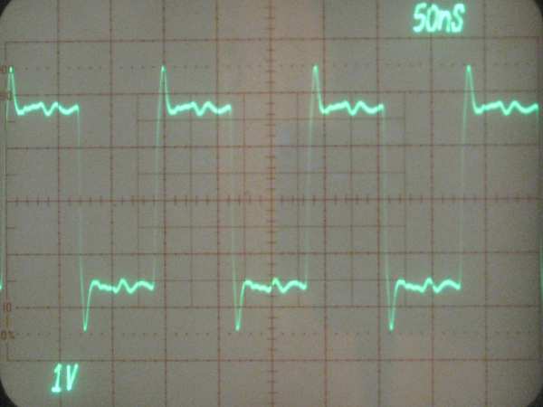
The ‘scope shot shows the output, which is a reasonably clean 3.3 V CMOS signal. There is almost a volt of overshoot on the transitions, which is a little concerning, but I am not too worried about it at this point. The CMOS edges are fast, making overshoot understandable, and the size of the overshoot is likely to change as the VFO is integrated into the radio. I will worry about it later.
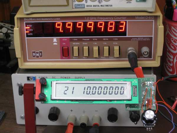
All in all, I have to say that the board works a treat. It is awesome to see 1 Hz tuning resolution and crystal oscillator stability coming out of a tiny 8-pin surface-mount part. I measured the frequency as being off by about 14 to 17 Hz at 10 MHz, which works out to about 1.7 ppm. Drift is confined to that 3 Hz range, at least when sitting on my basement workbench. The board does have a provision to calibrate out the frequency error, which I have not used yet. This much error really doesn’t matter.
The microcontroller firmware with the kit works well. The user interface is slightly unusual, with a decimal point used as an input cursor, but it works fine in practice. I do wish there was a way to configure band limits. The board has provisions for band selection, with up to eight bands possible. However, regardless of the band selection, the device will tune over its entire range. In a multi-band radio that is a poor idea, because it would be too easy to transmit at the wrong frequency and damage the final amplifier. With hundreds of on-board memories (100 per band, minus 20 reserved for setup), it would be nice if a few configuration memories were used to choose tuning limits for each band.
Over all I am happy with the board. It will serve just fine as my VFO.