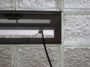
 One problem every ham faces is how to get his signal from inside, where the radios are, to outside, where the antennas are. A while back, I prototyped replacing a screen in my basement windows with a feedthrough panel. The prototype used hobby polystyrene sheets, which were easy to work with but far too flexible for the job. As the weather cooled, I removed it and closed the window, for fear some mice or other critters would find it a convenient way into our nice, warm house. Without a feedthrough, I had no way to use my antenna, so it was time to build a permanent version.
The window I chose is a typical basement window made of glass block, with a small section that opens.
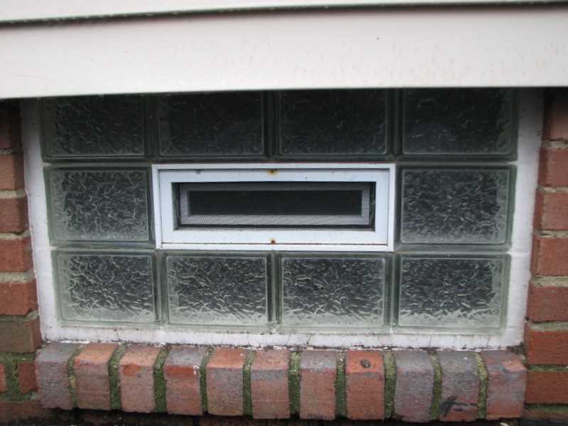
It didn’t take much work to remove the two screws that held the screen window.
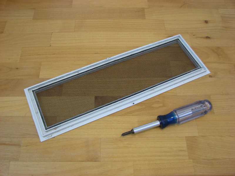
My plan was to cut a piece of acrylic (plexiglass) to replace the screen, but a friend one-upped that by giving me a piece of polycarbonate. This stuff is tough. A thicker version is used in bullet-proof windows! It will work fine for the job.
I put the screen on the polycarbonate for size.
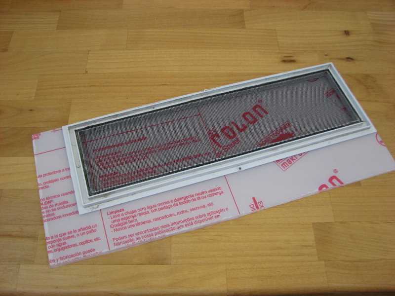
It’s perfect!
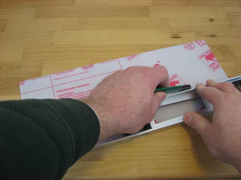
I marked the size I needed, along with the position of the screw holes, then used a scribing tool and a straightedge to scribe a deep line in the polycarbonate. The idea was to cut it like one cuts acrylic: by scribing it, then snapping it.
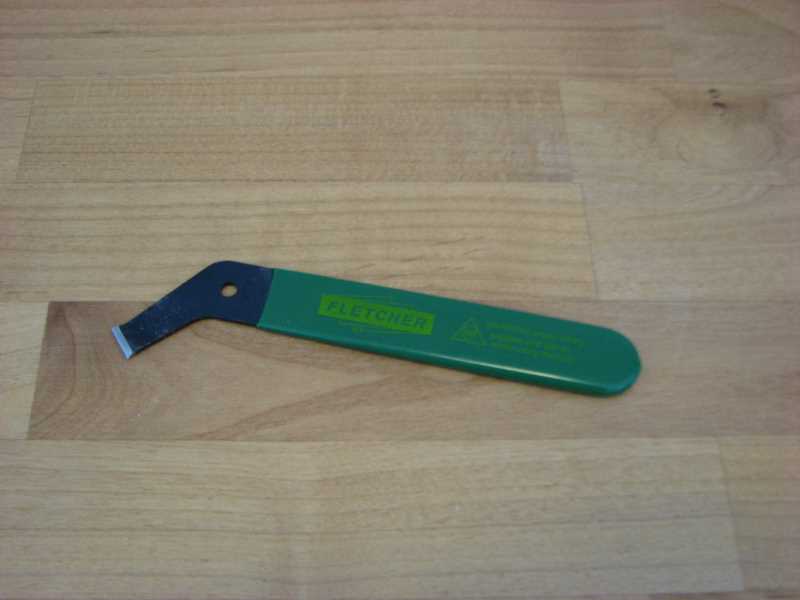
(This is what the plastic-scribing tool looks like. I found it in the window-repair section of my local hardware store.)
The polycarbonate was very hard to snap. I found out later that scribing and snapping is not the way to cut polycarbonate. In fact, it can shatter from this treatment. I should have cut it with a saw — I’m told table saws work particularly well.
In my ignorance, I scribed it deeper and deeper, trying to snap it over and over. Finally, it snapped. The material split a tiny bit along one edge (where the scriber had split and I had two parallel lines in the plastic), but in general the edge was clean and straight. I had scribed more than halfway through the sheet before it was ready to snap. Maybe I effectively sawed it after all…
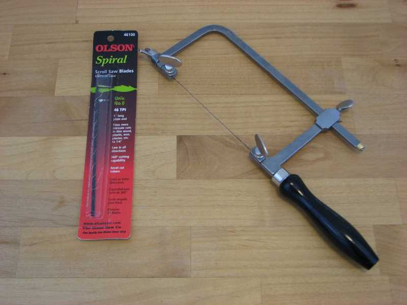
The next step was to make a hole for a BNC bulkhead feedthrough. The tool for this job was a jeweler’s saw with a spiral saw blade. These nifty blades are round and can cut in any direction without turning.
As a template, I used an electrical-box faceplate that had two holes for BNC feedthroughs like this. It came from the trash when an old coax-based (“thinwire”) Ethernet installation was upgraded to twisted pair.
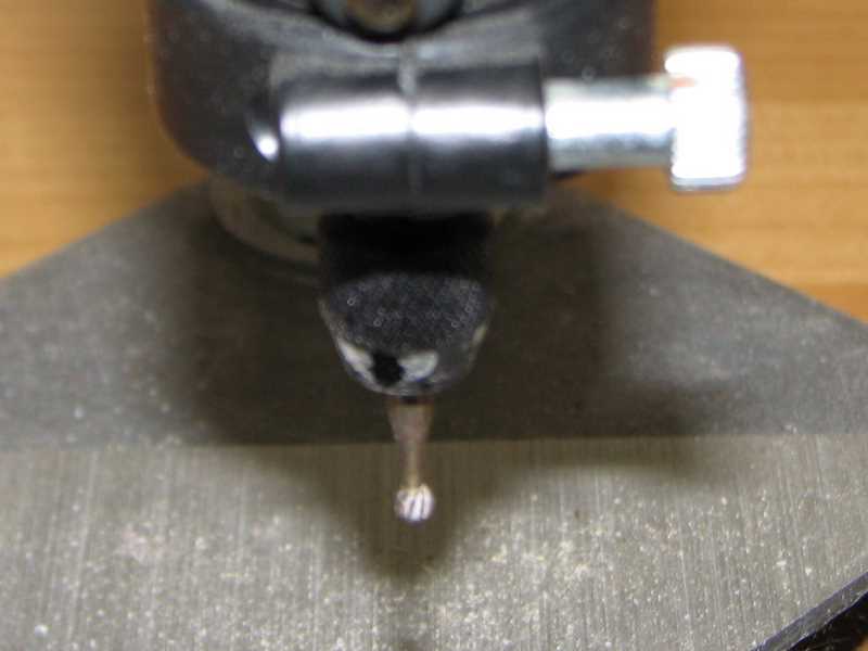
I drilled the hole with my little Dremel drill press. Some Googling of polycarbonate turned up recommendations against using a hand drill with it, because it can break bits if they aren’t held straight. I wish I had a real drill press, but this attachment for my Dremel tool seemed a good choice when I wanted to drill holes in homemade PCBs. It worked great for this job, too. A 1/8″ hole, the largest I had a collet for, was more than large enough to slip the saw blade through.
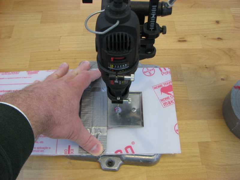
I also used the drill press to make two holes for the screws that will hold the panel in place.
As I sawed, I took care not to run the blade right against the template. It is stainless steel and would have dulled the blade much faster than the polycarbonate. In any event, I also had trouble turning one corner and needed to clean that up as well.
I set up the Dremel with my favorite burr bit, which looks like it needs to be replaced soon. It went through the polycarbonate like butter, quickly bringing the edges of the hole out to match the template.
I removed the template and tried the BNC bulkhead feedthrough for size. It fit perfectly! My past includes many a panel with misshapen holes that barely fit their intended connector, so this was surprising but welcome. I guess that’s what I get for never using a template before. The feedthrough I used was the former resident of the faceplate-turned-template.
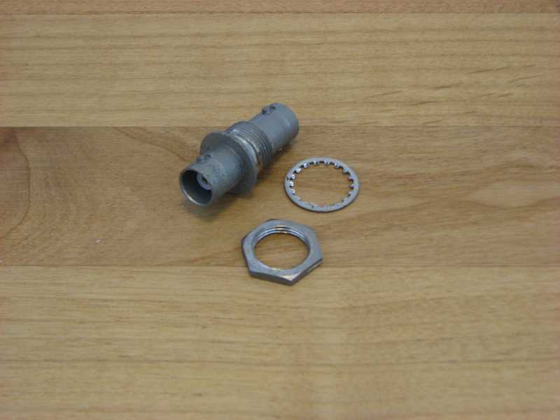
Now, one thing to mention here… I took care to put the nut on the inside of the panel. I used Coax-Seal on the outside connection, to prevent water ingress, and that stuff is messy and a bother to remove and replace. By putting the nut on the inside, I can remove and replace the feedthrough window without disturbing the Coax-Seal. That might be handy when I cut a hole for another connection.
Finally, I put it all together. I pulled the protective covering off of the polycarbonate, installed the feedthrough for real, and screwed it in place of the screen window. It was a little dusty, so I cleaned it before I installed it. Now it is so clear that the coax looks like it floats in space.
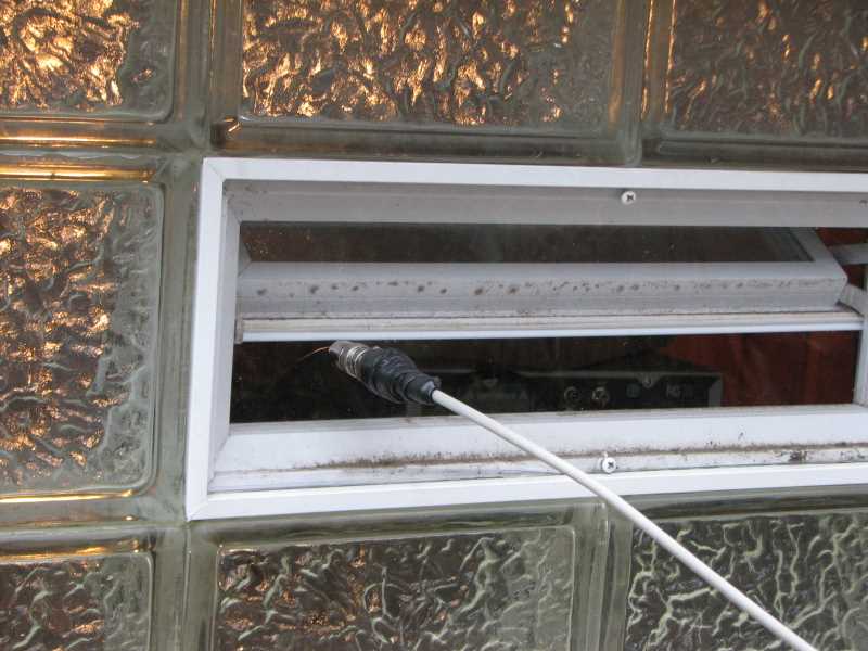
The clearance between the internal, movable window and the feedthrough window is enough that I can close the window after disconnecting the internal coax. (I figured that out with the polystyrene prototype.) That’s good for energy efficiency. The panel fits tightly enough that I don’t feel a draft, and I could always add weather stripping, but it’s still only a single-paned window. The moveable window behind it is double-paned.
The picture above shows the Coax-Seal, too. My technique for that, which I learned from the hams at the Case Amateur Radio Club, is to first wrap the connection with electrical tape, with the outer end folded over a bit to make a pull tab. Cover the tape with Coax-Seal, with the Coax-Seal extending a bit past the tape on each end for water-tightness. When you want to remove the connection, you can cut almost all the way through the Coax-Seal with a sharp knife, split the rest open like peeling an orange, and remove it down to the electrical tape. Next, unwrap the tape started at the pull-tab. The tape will take the perpetually sticky Coax-Seal residue with it, leaving a clean pair of connectors ready for reuse.
Jay Eiger was a font of wisdom for this project and also gave me the polycarbonate. Thanks, Jay!


