The BITX 40 is all about modifications. The design itself is “cheap and cheerful”, and the circuit board is laid out to invite changes and experiments. I have a list of quirks I intend to fix in mine, and with that the mods began.
First up was a misalignment of the BFO. Each BITX 40 uses a set of 5 matched crystals, four for the IF filter and the fifth for the BFO. The BFO is set up to pull the crystal frequency slightly to put the audio passband in the right place, or at least it is supposed to. On mine, the BFO frequency was just inside the IF passband.
Having the BFO in the wrong place had several consequences. First, receive audio was bassy, running from about 0 Hz to 1800 Hz. This transmits audio frequencies that are not useful for communications and omits the ones around 2 kHz that are especially important. Worse, the passband actually stretch below 0 Hz, into the upper sideband, which meant that my transmitter was not suppressing the carrier. It was sending VSB, vestigial sideband, not SSB. That may be fine if you’re a TV transmitter, but it’s not the kind of clean SSB signal hams expect.
One solution, which Wayne NB6M used on his BITX 40, is to change the “pulling” capacitor in the BFO to put the frequency where it belongs. Instead, I replaced the BFO entirely with a spare channel on the Si5351 frequency synthesizer.
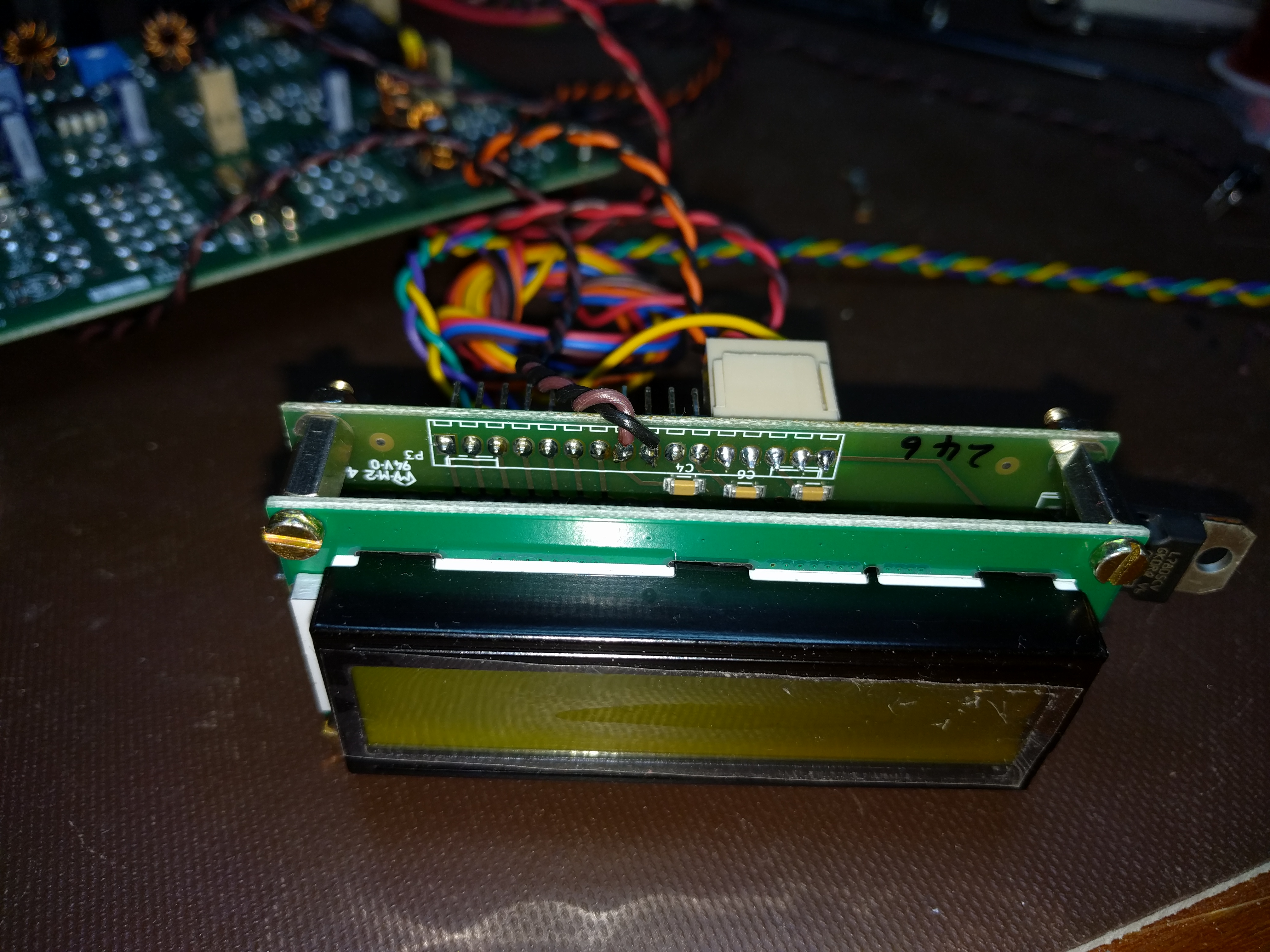
I started off by attaching wires to pins 8 and 9 of the Raduino board. These are Si5351 channel 0 and ground, respectively. For quick progress, I used a twisted pair. When I box it up, I will switch to coax and use a connector to make maintenance easier.

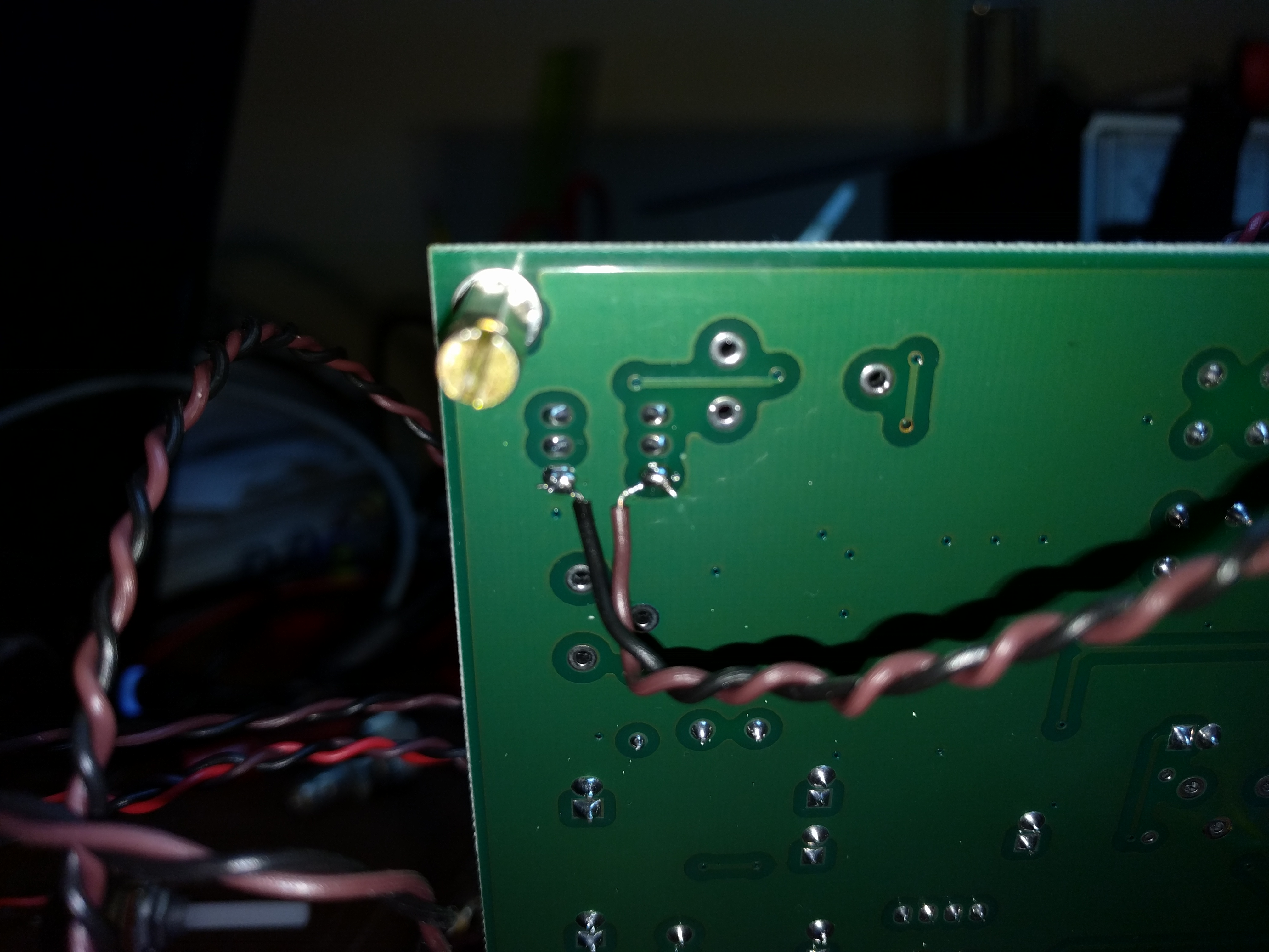
At the other end, I attached the wires to pins 1 and 6 of T4. This supplies the BFO to the second mixer.

Finally, I unsoldered R101 and C106 to remove power from the analog BFO and disconnect it from the second mixer.
With the hardware work done, I turned to the Arduino code. I downloaded Ashhar Farhan’s original bitx40 sketch and added one line of code near the bottom of setup().
si5351.set_freq(bfo_freq * 100ULL, SI5351_CLK0);
Then I turned it on, saw that the BFO was now too far above the IF passband, and with a couple of experiments, came up with the following edit near the top of the sketch:
#define INIT_BFO_FREQ (11997000L)
unsigned long baseTune = 7100000L;
unsigned long bfo_freq = INIT_BFO_FREQ;
With that, I was done. The rig sounds better and works better. I still haven’t transmitted, though. That will take one more mod which I will write about next.
Hi Stephen
Nice job! Sounds similar to my adventure with the raduino! In my code I used a list of variables…
long cal = 15400;
long LO = 4865000;
long vfoA = 7100000;
long vfoB = 14200000;
int ssb = 2000;
int cwF = 800;
long IF = 12000000;
with ssb representing the offset from the IF.
(cal, ssb, cwF & the VFOs are stored in EEPROM via a put statement in a “save settings” routine later on in the code…)
73s de Noel, ZL1NC