Are you the kind of tinkerer who has a few unbuilt kits sitting around? I mentioned last week that I want a faster way to get on the air than a designed-from-scratch SDR. If I stick to my current course, I may miss the peak of this solar cycle. It turns out that I have had an R2 receiver and a T2 transmitter kit on hand for… well, a very long time. If I recall, I bought them as soon as they were available in 1994.
These are very neat radios. Rick Campbell, KK7B, set a goal of pushing the state of the art in direct-conversion receivers. His series of high-performance receivers includes the R1, R2, R2pro, miniR2, microR2, and microR1. The R2 family are single-signal direct-conversion receivers, and the T2 and microT2 are companion transmitters.
The T2 uses the phasing technique to generate single sideband. In this technique, the audio signal is passed through a filter (or a pair of filters) that generate two signals 90 degrees out of phase. These are mixed with local oscillator (LO) signals that are also 90 degrees out of phase. When the mixer products are summed or subtracted, a miracle of trigonometry occurs, producing a clean single-sideband signal. As long as both sides of the system have closely-matched gains and the 90 degree phase shifts are very accurate, the opposite sideband is suppressed by 40 dB or more.
I decided to build the T2 first. Rick’s layout style is very dense, and I wanted to try the board with fewer components first. These are through-hole boards with the component holes falling on an 0.1″ grid in both directions. With only two exceptions, all of the resistors and diodes are installed “standing up”, with their leads 0.1″ apart and 0.1″ spacing to neighboring parts. The T2 board has no silk-screen, making construction that much more challenging. In any event, a fine-tipped iron and small-diameter solder (I chose 0.025″) are the tools of the day.
Rick suggests stuffing all of the parts before soldering any, as a hedge against putting them in the wrong holes. Then he recommends soldering and trimming the leads in rings from the outside in. I tried thaat, and it worked OK. For the R2, I will probably mount some of the trickier components individually, then switch to Rick’s method for the rest.
As you might expect, I had a few problems with solder bridges, but nothing a little solder wick couldn’t clean up.
Although there was no visible tarnish on this 17-year-old board, I did notice that the solder didn’t wet the pads as well as usual. Eventually I thought to start adding flux with the flux pen that I use for surface-mount work, and that did the trick.
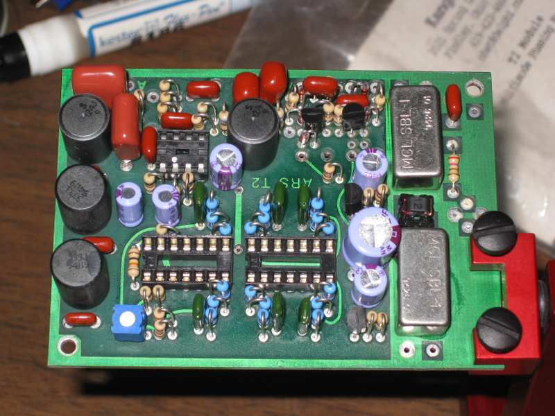
Here is my handiwork. I’d like to solder as beautifully as Tom, the electronics tech I work with, but for basement tinkering this will suffice.
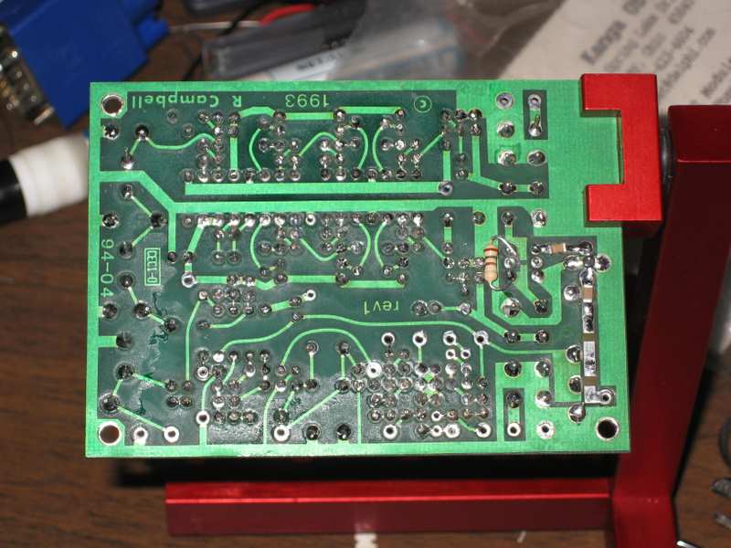
The T2 needs one more once-over for bridges and cold joints, then I’ll apply power and see what happens!
Links:
 “Honey, the package you’ve been waiting for from Hong Kong is by your computer,” said my dear wife shortly after I got home from work on Friday. Even better, a few minutes later she suggested that I spend the evening in the basement, building up one of my new boards. I have a wonderful wife!