Rethinking Arduino: A review

I’ll admit it, I was wrong. I’m an engineer by profession, and one for whom designing a microcontroller-based PC board is old hat. I used to look down my nose at Arduino. Its populist appeal and simplified programming language made it a toy in my eyes. I have worked with other boards with similar goals of broad appeal that were poorly designed, with compromises that made the boards unusuable or that overstressed components, making them unreliable. Above all though, “real” engineers design boards for microcontrollers, and they program the microcontrollers using JTAG connections and arcane syntax — or so I thought.
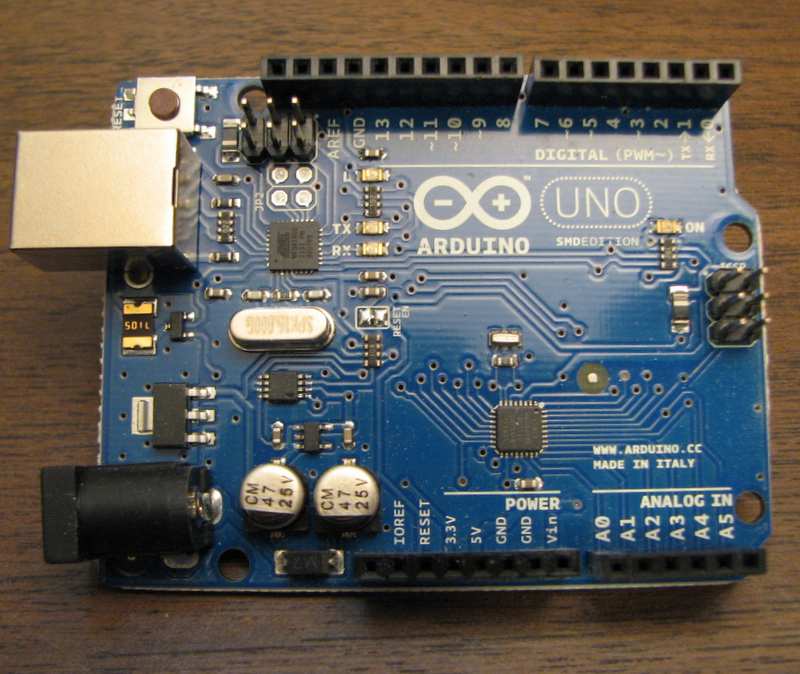
Arduino Uno circuit board

Then a few weeks ago, I was given an Arduino. My perspective has shifted. Arduinos may be populist, they may be the Radio Shack Engineer’s Notebook of the microcontroller world, but they’re also well-designed development boards worthy of any engineer’s attention.

My Arduino came as part of a Sparkfun starter kit, which includes a breadboard, hookup wires, an RGB LED, packs of 1K and 10K resistors, and some fun sensors to play with, including a touch-sensitive resistor and a bend sensor. It amounts to a microcontroller-based building set, and would particularly appeal to anyone who wants to experiment with microcontrollers without having a specific project in mind. Though my son and daughter will be too young for the kit for a few more years, it caught my eye as exactly the sort of thing I might give to one of them to help them learn about what goes on inside a computer.
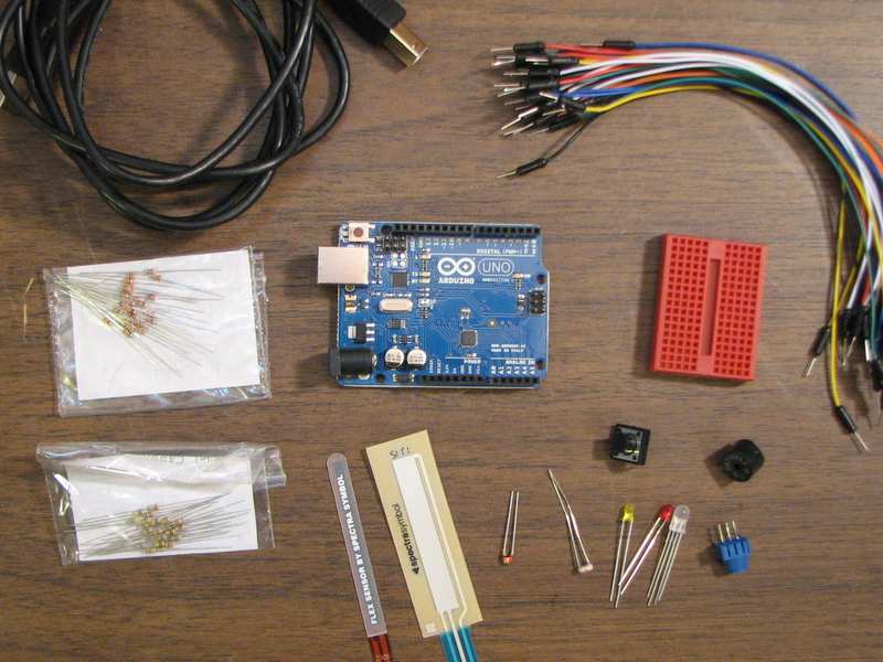
Sparkfun Starter Kit contents

I set the accessories aside and focused on the Arduino, an Uno model in this kit. Arduino’s current foundation model, the Uno includes a Atmel Atmega328 microcontroller, on-board power supplies (5V and 3.3V), a USB serial interface, a general-purpose LED, and female sockets that break out the microcontroller pins.

The Atmel processor is surprisingly speedy. It has an 8-bit CPU running at 16 MHz, which was plenty of processing power for the things I was trying to do. Perhaps the biggest limitation of the processor is its 2K of RAM. The 32K of flash on-board is great, and conservative programming techniques can fit a surprising amount of functionality into 2K of RAM, but sometimes it’s easier and faster to use a controller with more RAM.

The USB serial interface was a surprise as well. It is implemented by a second, smaller Atmel CPU, programmed to operate as USB-to-serial interface chip akin to the popular FTDI FT232 family. According to Arduino’s creators, the Atmel CPU was less expensive than the FTDI equivalent. Beyond being an interface, the second CPU has a USB bootloader and an ICSP (in-circuit serial programming) header of its own, so it can be reprogrammed just like the Atmega328. The USB CPU is in a tiny QFN package, and most of its I/O lines are not brought out. Still, the ability to reprogram it opens up a lot of interesting possibilities.

Arduino’s native programming environment uses a simplified C-like language. Since I’m comfortable with standard C and prefer test-driven development, I followed Nick Christensen’s detailed instructions on how to set up an Arduino development environment with gcc, Unity, and CMock. The gcc compiler is an industry standard tool these days, and I like Unity and CMock for unit testing.

Then I found out I was a snob. The Arduino wasn’t a toy. As I dug into its schematic and capabilities, I found a well-designed little development board. It was designed with cost-reduction in mind, for sure, but without losing sight of giving access to the entire capabilities of the processor. One processor pin drives an LED, for instance, but that line is also brought out to a header, making it available for other uses. The analog input pins are brought out without analog buffering, so they are available for digital I/O. Even the serial interface pins used to download code over USB can be repurposed.

There are other low-cost development boards, some directly competing with Arduino and others aiming for a slightly different audience. Here Arduino’s advantage is its popularity. Between Radio Shack and Micro Center, I can buy an original or cloned Arduino at retail from at least four stores within three miles of my house. That is surely not true for the entire world, but Arduino and software-compatible clones are also readily available online.

For my last small project, when I needed a microcontroller, I picked an inexpensive MSP430F2011 because TI’s EZ430 USB stick (which was a freebie from TI) could serve as the programmer. Next time, there’s a good chance I will use a genuine Arduino, one of the clones, or maybe just use these development tools with a plain Atmega328.

Yep, Arduino is worth a look, even for those used to the traditional “professional” world of microcontroller design.
Itead Studio’s Open PCB exchange: how it worked out

The boards I ordered last month from Itead Studio arrived with something extra: someone else’s boards! No, it was not a mistake, but a 10-cent option that I could not resist: the Open PCB service. For 10 cents above the cost of a prototype PCB order, Itead fabbed two extra boards of my design. Those boards went into a pool of boards from the other Open PCB participants, then Itead sent each of us two random boards from the pool. All participating boards are supposed to be open source. Sure, there is no guarantee that the boards will be at all useful to the recipient, but who knows, maybe something nifty will arrive!

I ordered the Open PCB option with my AK5388 ADC board. Along with my 8 copies of the board, I received two boards from strangers. Both are 5 cm x 5 cm, which is likely a popular size for Itead because it’s the maximum size for their cheapest PCB fab deals.

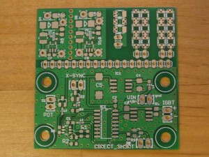
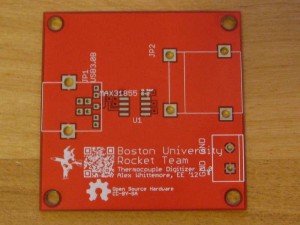
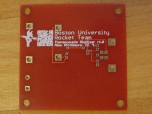
Boston University Rocket Team thermocouple digitizer PCB, top side Rocket team's thermocouple digitizer PCB, bottom side

The first board is a thermocouple digitizer from the Boston University Rocket Team. The team has posted the schematics, layout, and Gerbers online on GitHub. The board was clearly labelled, making it easy to find the documentation in Google. It even had a QR code. though the pixels were blurred by the silkscreen and my phone was unable to read it. It’s a great idea for open source hardware, though, and would probably work if it were a little bigger.

The design uses a single MAX31855 as a thermocouple-to-digital converter. This is a neat chip that contains a thermocouple amplifier, cold-junction compensation, and a 14-bit ADC all in an 8-pin SOIC. That’s a ton of analog circuitry condensed into a single chip! It can cover temperatures from near absolute zero to molten metal, with quite respectable accuracy and resolution.  The board runs the chip’s Serial Peripheral Interface (SPI) to a USB 3 connector, wired in a non-standard way that carries power (12V, 5V, and 3.3V) and an SPI bus.

The Rocket Team has chosen an interesting mission. They don’t fly rockets, but rather research the design and performance of hybrid rocket motors, including firing them on a static test stand. They build their own instrumentation, all open source hardware, and this board is part of that package. I can see why they would be interested in accurately measuing the temperature of very cold and very hot things!

The board actually has some potential to be useful to me. I don’t need a thermocouple interface right now, but I can imagine using for one down the road to monitor a reflow oven or to manage the heatsink temperature in a linear amp.

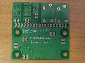
Ville K's board, top side  Ville K's flash power control board, bottom side

The second board is a bit of a mystery.

On first inspection, I was puzzled by the single-row header right across the middle and the smaller row of holes at the upper-left side. Eventually I noticed that there are no traces running to either, so it’s likely that they are perforations to simplify cutting the board into three pieces.

The bottom portion is the least obscure. It bears the labels “Flash power control” and “X-SYNC”, so it must have something to do with photo flash. Beyond that, I’m stumped. A two-pin header for an IGBT (a three-terminal device) particularly leaves me scratching my head. The designer did a nice job of bonding his top-side ground pour to the bottom-side ground plane with plenty of vias, including all around the edge of the board.

On the upper right, there are two copies of a circuit, separated by a row of holes to aid breaking them apart. The circuit has a transistor in SOT-23, a diode, a few capacitors, a resistor, and what is likely an IC in a small 5-pin package. Looking at the topology, I think the circuit is a boost converter, at least if the unlabeled two-pad component on the center left is an inductor.

The patterns in the upper right corner are even harder to understand. They look like series chains of something, maybe resistors or LEDs. The vias in the pads and the wide traces indicate that the designer was concerned about resistance, inductance, or heat dissipation. Since the three-device chain (upper center of the board) has the triple vias to back-side copper, but does not use the copper to interconnect, I would guess heat sinking is the concern. It could be a challenge to reflow the board with the open vias in the pads, but it’s probably meant to be hand-soldered. When hand-soldering, one can keep feeding solder until the holes have wicked up their fill.

I sent some e-mail to the address in the silkscreen but got no reply. Google searches on other likely terms turned up nothing. I’m left with a board and guesses.

The Open PCB  exchange is a great idea, and I’ll happily participate again in the future. The thermocouple board is an example of how it can go right. I got a well-documented board that led me to find out about the Rocket Team’s interesting work. In contrast, the Flash Power Control board is an example of what can go wrong. There is nothing to stop someone from entering an undocumented PCB in the exchange, getting documented and interesting boards but failing to repay the favor. Still, I like seeing what other people are doing and hopefully two other people enjoyed seeing what I’m up to. For 10 cents, less than a 1% increment on the cost of a PCB order, it’s worth it.

Have you tried Open PCB, and how did it work out? Are you able to shed any light on the mystery board?  As always, comments are welcome!

Trying out Itead Studios’s PCB prototyping service

I’m working on building a breakout board for the high-performance AK5388 audio ADC. In my last post, I revised the schematic to help with the PCB layout and test-fit the key components on a printout of the board.

The next step was to order the board. Laen’s PCB order is taking a hiatus this month. Feeling impatient, I decided to try one of the Chinese options: Seeed Studio’s or Itead Studio’s PCB fab services. They offer prices as low as $9.95 for 10 copies of a 5 cm x 5 cm board. Unfortunately, the ADC board is 4.9 cm x 6 cm. That extra centimeter nearly doubled the cost of the board, because I had to buy a 5 cm x 10 cm package. At least one dimension was still below 5 cm!

My son wandered in while I was comparing prices. He asked, “Is your circuit board going to be purple?”  I told him that no, it was probably going to be green.  “I think it should be red!” he said.  “What the heck,” I thought, and clicked on the button for Itead’s color PCB service. The deal was $23 for 8 boards. That compares with $18 for 10 boards if they are green. Since both 8 and 10 boards are more than I need, it’s basically $5 extra for the custom color. I went for it.

For what it’s worth, one difference between Itead and Seeed is that Seeed only offers 50% electrical testing for their base prices, with 100% testing costing more. Itead has 100% e-test with their base prices. Itead and Seeed are having a bit of a price war over these PCB services, so their offers may well have changed by the time you read this.

Itead is offering an interesting bonus deal with their PCB services: PCB sharing. For a token 10 cents above the cost of the PCB service, they will send me two random boards from other designers. In exchange, they will send two additional copies of my board to other sharing participants. There is no guarantee the boards will be remotely useful to the recipient, but for 10 cents, how could I resist?

(By the way, if you’re reading this because you saw the skywired.net URL on a board Itead sent you, please drop me a note! I’d love to hear who you are and what you’re working on.)

I expected roughly a five day turnaround from Itead, and was disappointed when after five days, I received an e-mail that the fab had rejected my Gerber files. Itead wants the board outline on at least one Gerber layer. Now, both Laen and Sparkfun’s BatchPCB accepted the groundplanes on my boards as the outline, so I didn’t expect trouble from Itead. However, they were certainly within their rights to ask me for a correction. It was quick to add it, and a few hours later they told me my new Gerbers had been sent to the fab.

I’m still waiting for the PCBs, which were shipped Wednesday. Now I have to wait for them to come by airmail from Hong Kong. It’s hard to be patient!

Cool open source hardware demos from OHS 2011

The Open Hardware Summit closed with an evening reception, with hors d’oeuvres tables tucked in amidst dozens of demos strewn around a large room at NYSCI. From an Ethernet-connected Arduino to a visual musical instrument, here are a few that caught my eye.

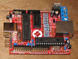
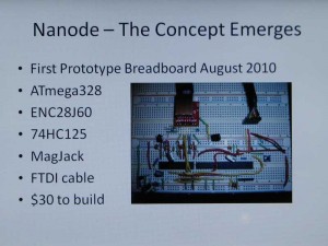
First up was the Nanode from Wicked Device. This board is an Arduino clone with built-in Ethernet. It would make a great platform for any control tasks that needed to interact with other Internet-enabled devices.

Nanode PCB Nanode concept slide

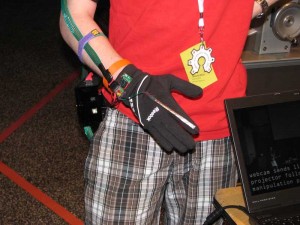
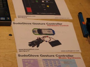
Right around the corner, an RC car was racing around the floor under the control of a subtly gesturing Jeremy Blum and his SudoGlove.

Jeremy Blum's SudoGlove SudoGlove explanatory slide

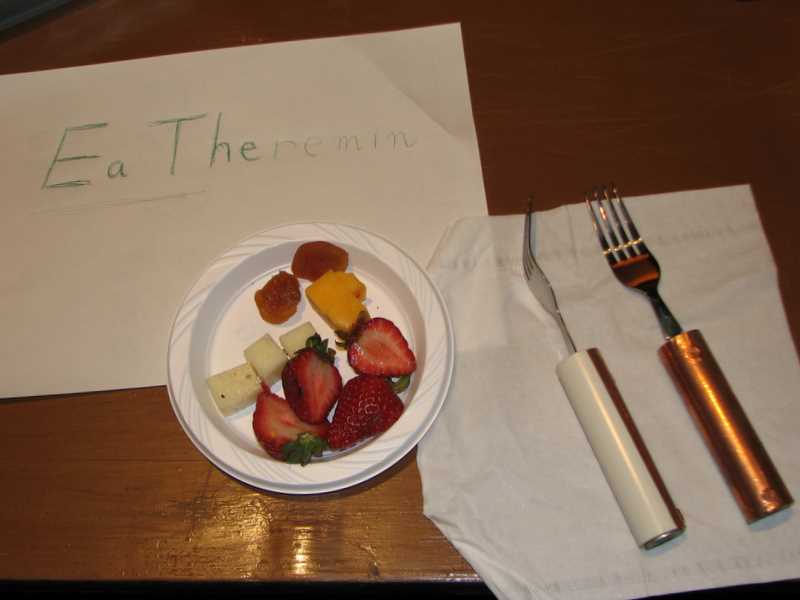
This curious device is titled “EaTheremin”. The forks had circuitry concealed inside the conductive handles. When one ate with them, current flowed from tines to handle via the diner’s body, causing a variable pitch to be emitted by a nearby speaker. I have to admit that I don’t quite get it, but I can appreciate the creativity of the EaTheremin’s inventor.

EaTheremin

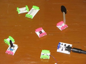
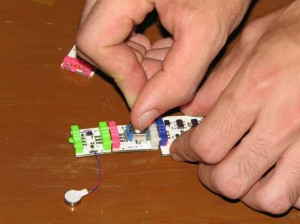
LittleBits had a table with their long-awaited magnetic circuit construction toy. The idea is to connect a series of small circuit boards to build interesting circuits. The boards hold themselves together with magnets, and keying in the plastic fittings at each end mean that incompatible components cannot connect to each other.  LittleBits founder Ayah Bdeir is one of the OHS organizers.

littleBits boards littleBits in use

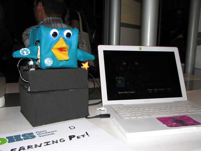
The Learning Pet is a cute robot that augments educational games for children, developed by Erin Kennedy, better known as robotgrrl. The Pet can pivot, flap its wings, and change its expression in synchrony with events in a computer game.

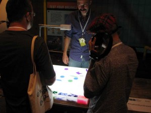
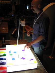
Finally, Ryan Raffa’s RhythmSynthesis musical instrument was always surrounded by a crowd. By placing colored geometric shapes on the lightbox, one can compose repeating rhythm tracks. The color of each shape sets the pitch, the area selects the octave, and the outline, position, and possibly the rotation of the shape change other aspects of the sound. The sounds from each shape are played as if by an old-fashioned radar beam sweeping out a circle under the light table. Ryan developed RhythmSynthesis for his MFA in Design Technology, so plenty of details are in his thesis paper.

OHS attendees enjoying RhythmSynthesis Ryan Raffa demonstrating RhythmSynthesis

Here is a video of RhythmSynthesis in action, from the RhythmSynthesis web site:

These are but a few of the many tables at the reception, all with abundant creativity.

Open Hardware Summit 2011

Last week I took a trip to New York to attend the Open Hardware Summit. The talks were outstanding, and it was great to be in a crowd of extraordinarily creative people. While the open hardware world has its share of engineers, both amateur and professional, it also has artists, which makes for some interesting fusion.

Furthermore, the presentation skills of the speakers ranged from good to outstanding. It was a pleasant shock to watch one excellent talk after another. I must have been lulled into complacency by having seen too many boring talks at scientific conferences.

The Summit was held at the New York Hall of Science, which two days later hosted Maker Faire. As I walked down the street from the train station to the museum, I knew I was getting close when I saw these over the trees. That’s a Mercury and a Gemini capsule perched high on their boosters.

Rockets at the New York Hall of Science

Why the Hall of Science, one might ask? Eric Siegel, the Director and Chief Content Officer, welcomed us to the conference by explaining that NYSCI is about getting people interested in science, and he sees the open hardware movement as doing the same.

The keynote talk was from 4/5 of the Arduino team, who were entertaining and engaging speakers. A few memorable quips:

  • (When starting an open hardware business) “Hire a lawyer. You don’t know why but she does.”
  • “If you have a company with 5 people in 3 countries, you are a multinational corporation.”
  • (On the popularity of names ending in -duino) “We named the Arduino after our favorite bar. … The worst one was one morning when I found in my e-mail an announcement of a board called “Sanguino”. If you get the accents right, in Italian, that means ‘I am bleeding’.”

Bunnie Huang (of Chumby fame) gave a great talk on the end of Moore’s Law and what he sees as the future of open hardware. Moore’s law drives a very short market cycle for new designs, which means that by the time an individual hacker can build something interesting, it has been obsoleted by products from big corporations. In places like Shenzhen, though, the use of trailing-edge technology means small shops can innovate and still be competitive. Once Moore’s law runs into fundamental physical limits, Bunnie believes market cycles will slow and small innovators participating in the open hardware world will be able to compete more and more effectively with the big guys.

Bunnie was the first presenter to use his own hardware on stage.  He funneled his presentation through NeTV, an HDCP video overlay board. Bunnie had it set up so that people in the audience could text or tweet messages, in real time, to a scrolling banner at the top of his slides.

At lunch, OpenROV‘s Eric Stackpole and David Lang took up a strategic position next to the catering line with some of their underwater robots.

Open-source underwater robots

After lunch were more great talks. Surprising to me was the talk by Bruce Perens, the founder of the Open Source Initiative and one of the key players in the emergence of the widely-used open source software licenses used today. I thought he would have something to say about hardware licensing, but instead he talked about the ham radio satellites and what AMSAT and TAPR have done to develop and release open-source hardware designs.

James Bowman followed up with a great talk about the Gameduino, a board that can be used to play video games with an Arduino or other small microcontroller. His talk was about the development of Gameduino, which went from Kickstarter to a shipping product in three months. More than demonstrate his product, James used it as the sole device for presenting all of his slides. Here’s a Gameduino, as seen on a Gameduino:

The Gameduino uses James’s impressive J1 Forth CPU as part of its hardware. The J1 is on my list of things to try out.

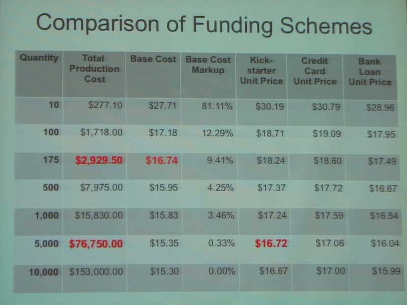
Bryan Newbold gave an insightful talk about the economics of small-quantity price breaks. Being at Octopart, Bryan has access to a massive component price database, which he used to illustrate a number of points about small-run manufacturing, as is typical for an open source hardware startup. One of his most striking slides was this, which illustrates the effects of the hidden costs of various funding sources. In order to get the same cost per unit if selling 175 units with cash funding, a startup might have to sell 5000 units with Kickstarter funding. That’s a sizeable difference, and it’s caused by the interaction of quantity price breaks with the direct and indirect costs of various sources of funding.

Chart

Mitch Altman brought the plenary session to a close with a talk about his experiences turning the TV-B-Gone into a product. Mitch is an outstanding and entertaining speaker. One of his gems: “Hi, I’m Mitch Altman. I turn off TV’s for a living, and I LOVE MY JOB.”

The day finished with cocktails and demos from dozens of hackers and makers. I’ll have more on the creative things I saw there in my next post.

Want to share your thoughts about open source hardware? Were you at OHS? Comments are welcome!