AK5388 ADC breakout board update

For the last month or two, a breakout board for the AKM Semiconductor AK5388 analog-to-digital converter has been my main project. Here’s an update on where it stands.

When I last posted about the board, I was waiting for parts to arrive so I could check their fit on a printout of the PCB. After the capacitor footprint error on the FPGA breakout board, I was feeling a bit cautious. The parts arrived and fit fine!  I checked out the ADC on its QFP footprint, and it was perfect. Then I tried the big capacitors on their EIA 3216 footprints, and those were fine, too.

Fixing the schematic

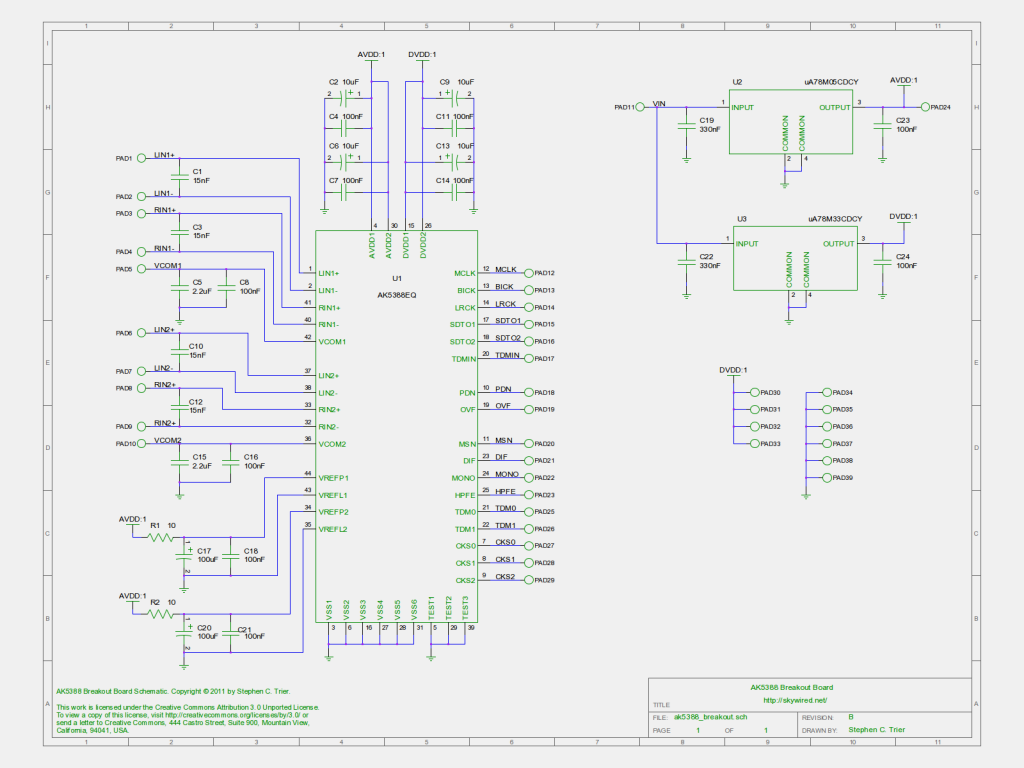
AK5388 breakout board schematic, revision B

I ran into some problems with the schematic when I did the PCB layout. One problem was that multiple pads named “GND” or “DVDD” were consolidated into one. A second problem was that the names I had assigned the pads were not visible in PCB, meaning I was in for a slow process of finding each one on the schematic in order to add the right label to the PCB’s silkscreen. I found a great solution, though.

The fix to both problems was to name the nets, not the pads. I restored all the pads to their boring PAD1, PAD2, … reference designators and named the schematic nets after the signals. Now, when I hovered the cursor over one of the pads in PCB, a little tooltip popped up and told me the net name connected to the pad, among other things. Labelling all of the pads took only a few minutes. I wish I had known about this trick when I did the A3PN250 FPGA board!

Secondly, using conventional reference designators to name the pads solved the problem with the DVDD and GND pads.

These changes resulted in the rev B schematic. A PNG version is above, and I’ll post the editable gschem version on the AK5388 breakout project page.

I have ordered the boards, and I will have more to say about that next week.

What do you think? Comments welcome!

PCB routing techniques for ADCs

PCB layout is fun, especially when you are trying to eke the best performance out of a component.  Last week, I finished the PCB layout for the AK5388 analog-to-digital converter (ADC) I chose for my digital ham radio transceiver project. Let’s take a closer look at some of the design details…

My top priority was to keep digital lines away from sensitive analog signals. The quickly-switching edges of digital signals carry lots of high-frequency components, which readily couple into any neighboring line. It’s best to keep this high-frequency crud away from quiet analog signals. It’s not great to let it couple instead into other digital lines, but digital inputs are pretty tolerant to it and rarely have problems.
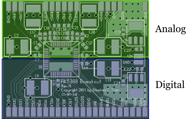
AK5388 board with an overlay showing how the analog and digital sections are separate.

The AK5388 pinout helps a lot with this separation requirement. As is done in many ADCs, all of the digital pins are on one side of the chip, and all of the analog pins on the other. When laying out a mixed-signal board (that is, one that has  both analog and digital elements), I like to draw a line across the board before I even start to place the parts, with all analog components going on one side and all digital on the other. As the placement and routing progress, that line will move and may even change into a zig-zag, but the idea remains: Keep the analog stuff on one side and the digital on the other.

On the AK5388 breakout board, the analog-digital border remains a straight line. Everything in the top half of the board is analog, and everything in the bottom half is digital.

Another reason to have a clean split is the return currents and their IR drop. Remember that current flows in a loop. When any of those digital lines changes state, it charges a small capacitance at the other end, and the current used to do that charging flows back through the ground plane. At high frequencies, that return current is largely confined beneath the digital line that caused it. On top of that, the return current causes a voltage gradient underneath it, thanks to Ohm’s law and the resistance of ground. (V = IR)  This voltage gradient can act as an additive noise source on analog signals that are routed near it. The careful split in this board’s design will help keep the digital return currents from affecting the analog signals.

Another feature of the board is that it has local analog and digital power supplies for the ADC. The power supplies are located in their own area, again to try to limit noise caused by the return currents. In the picture below, the power supplies are highlighted in yellow.
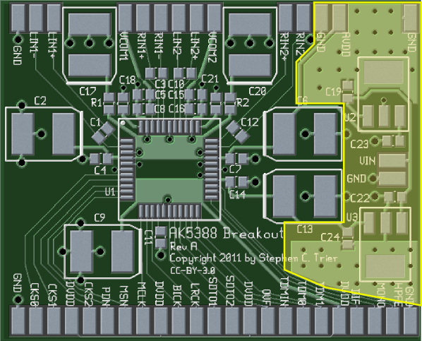
The AK5388 breakout board with the power supply location highlighted.

The voltage regulators used here (uA78M33CDCY and uA78M05CDCY) are in SOT-233 packages, which have a large lead on one side to help with heatsinking.  The board is laid out with some extra copper area to act as a heat spreader for each SOT-223, along with a bunch of vias tying the top-side copper to the ground plane. These vias have a thermal role, not primarily an electrical one, as they help transfer heat from the top-side heat spreader down to the ground plane to further spread it out.

Although there are ways to estimate the thermal performance of a heat-spreader design like this, I didn’t do them. Frankly, I don’t have any idea whether this board’s thermal provisions are adequate. Even at the bargain price of $5/square inch to have this PCB fabbed, adding copper just for thermal management gets expensive. If the heat-spreading area turns out to be insufficient, I’ll find a way to attach a heatsink to the top side of the regulators, solder a piece of brass to their large lead, or something along those lines to remove the heat more efficiently.

Finally, take a look at the decoupling capacitors. C4, C7, C11, and C14 are 100 nF capacitors, each on one power-supply input to the ADC. They are positioned as close to the ADC as I could manage. One could argue that their positioning is not quite perfect because there is a relatively long path from their grounded side to the closest ADC ground pin. It goes through two vias and the ground plane. I have never looked into whether this makes a significant difference. If you know, leave a note in the comments and tell me!

In any case, the 100 nF capacitors are multi-layer ceramic capacitors (MLCC), which have a low equivalent series resistance (ESR) and inductance (ESL). Those characteristics make them ideal for decoupling high-frequency noise on the power supply lines.

Next, C2, C9, C22, and C23 are big 10 μF decoupling capacitors. These are positioned a little farther away. They are aluminum electrolytic capacitors, which have a higher ESR and ESL than ceramic caps. (10 μF ceramic capacitors are expensive!) These capacitors are better for removing low frequencies, including the audio range, from the power supplies. For that reason, I did not see much harm in putting them a little farther from the ADC, with the extra inductance and resistance that implies. Besides, these things are BIG! If they were any closer to the ADC, routing the signal lines in and out would get pretty challenging.

One trick for getting the decoupling capacitors closer is to put them on the back side of the board. The distance through a via would be much shorter than the distance needed here. I wanted a single-sided design here, so that wasn’t an option, but it’s something to keep in mind.

I won’t claim that I know everything about designing for a high-performance ADC. In fact, it’s possible that someone more experienced is planting their face in their palm right now, saying, “I can’t believe he did that!”  (If that’s you, by the way, drop me a note to let me know what the problem is, would you?)  That said, what I did here is based on app notes and other materials from a number of semiconductor companies, including Analog Devices and National Semiconductor, and I think it’s pretty sound.

I ordered the parts for this board today. It doesn’t take long for UPS to get things to Ohio from Digi-Key’s home in northernmost Minnesota, but it’s always a long wait when I’m itching to try something out.

I’ll catch you next week with more on electronics, DSP, and ham radio.
PCB layout for the AK5388 ADC breakout board

I had some time to myself this weekend and was able to get the AK5388 breakout board routed. The board carries an AKM AK5388 audio DAC, which has 24-bit output and up to a 123 dB signal-to-noise ratio. My plan is to build up this board, evaluate it to verify that it works as I expect, then use it as the ADC stage in a DSP-based ham radio receiver.

Moving the schematic from gschem to PCB was really easy. This was my first time using PCB’s “Import schematics” command. It was a breeze, especially compared to the old way of doing it, the gsch2pcb command. That command worked well enough, but I could never get it done without checking the documentation or a howto online. “Import Schematics” required no such thing. Bravo to the PCB developers!

As with the FPGA board, I laid out the board with a solid groundplane on the back and all components and traces on the front. That way, it can be placed on a piece of copperclad board, for skywired construction, without risk of shorts to ground. It’s also good for noise performance.

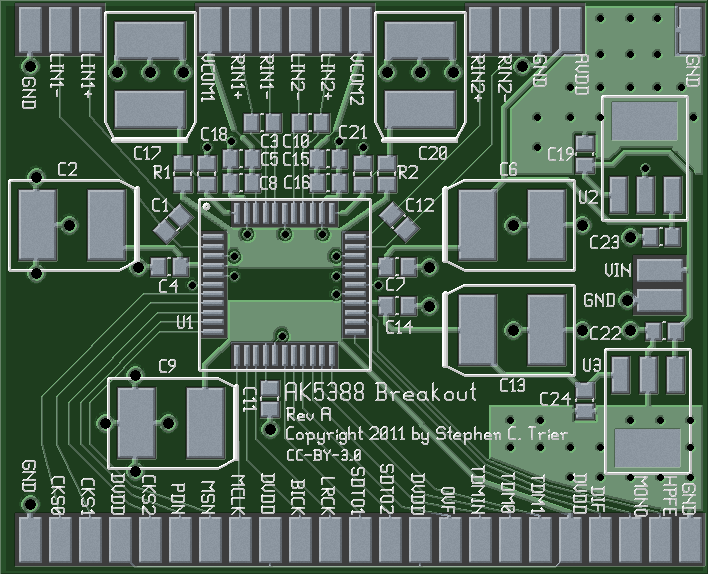
Photorealistic view of AK5388 breakout board, top side

The square chip in the middle (QFP, U1) is the AK5388. On the right edge are a 7833 and a 7805 voltage regulator, for the digital and analog power supplies, respectively. The board includes some heatsink area around the regulators (U2 and U3), with thermal vias to stitch the heatsink to the groundplane on the back. The rest of the components are decoupling capacitors, lots of decoupling capacitors, plus two resistors that also help control noise. A 24-bit ADC needs quiet power supplies!

As you might expect, the bottom side is kind of boring:

Photorealistic image of the bottom side of the AK5388 breakout board

That’s the ADC board so far. Although I have Gerber files now and could go order the boards, I’m going to order the parts first this time and test-fit them on a printout of the layout.

Crazy PCB Layout from the Big Hair Decade

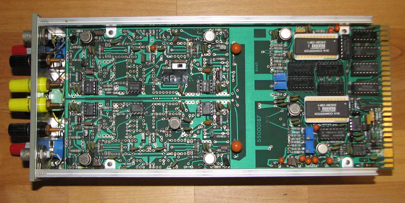
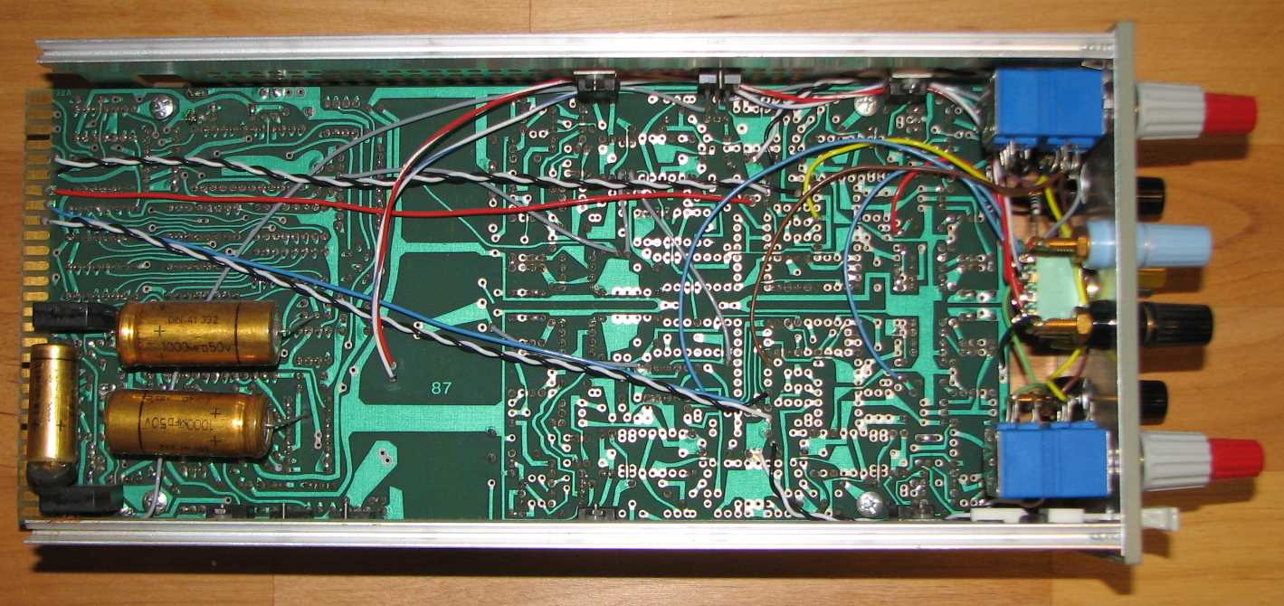
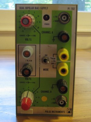
Check out the bizarre PCB layout on this power supply.  A Pulse Instruments PI-702, I bought it for a few dollars at a hamfest. It was made in the mid-80’s and plugs into Tektronix TM500-series mainframes. When I powered it up, BANG!, after which it had no output.  Here is what I found when I opened it up for a look:

The curvy, hand-taped traces are typical for the period, but look at how few components are in the two-thirds closest to the front panel compared to the number of pads! Plenty of those pads look like they have an 0.3″ DIP pattern, but have either discretes or nothing soldered to them.  The layout is also full of dead-ends and traces that don’t go anywhere, and there is no silkscreen.  The back third is neat and tidy — it is all a bit Dr. Jekyl and Mr. Hyde.

All of this leaves me wondering what the crazy layout is for! If it is meant to dissuade reverse-engineering, it might work (it worked for me, so far…), but who would want to protect something as simple as a linear power supply? It is even stranger that the digital-to-analog conversion circuitry near the edge connector gets so little of the board, and is laid out quite cleanly compared to the power supply.  I suppose that this might be a case of multiple models using a single PCB, but what a devious mind it would take to merge multiple schematics into something that looks like this!

The problem itself was easy enough to find. One electrolytic capacitor dried out and blew up. You can see it at the lower-left of the second photo. It will be easy to fix, assuming it didn’t take any other components with it.

The device itself is interesting.  It has three outputs, two of which are bipolar, each covering -25 V to +25 V continuously. They can be independently set with front panel controls, track an external input, or be controlled digitally. The bipolar outputs are limited to a wimpy 25 mA each, which is undoubtedly why it is called a bias supply. It also has a fixed +5 V output at up to 0.5 A.

Now I know that the 80’s were not only the decade of MTV and big hair, but at least one rather strange PCB layout.

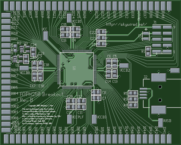
FPGA Breakout Board Layout

Here at last is the printed circuit board layout for the FPGA breakout board. I’m planning a series of projects involving FPGA-based DSP for ham radio, and in order to build them, I need an FPGA and a PCB on which to mount it….

The goals for this layout constrained it to be a nearly single-sided layout, …

Here at last is the printed circuit board layout for the FPGA breakout board. I’m planning a series of projects involving FPGA-based DSP for ham radio, and in order to build them, I need an FPGA and a PCB on which to mount it. In the last installment of the project, I presented the schematic for the breakout board.

The goals for this layout constrained it to be a nearly single-sided layout, with a ground plane on the back. That way, the board could be mounted directly on a piece of copperclad with no short circuits to ground. My budget limited me to a double-sided board, so all signal and power traces had to go on the top side.

That said, here is the layout, top and bottom.

FPGA breakout PCB, top side

Continue reading “FPGA Breakout Board Layout”