Teaching Electronics to a Preschooler

I was stuck. How do I explain decoupling capacitors to someone who doesn’t know yet what electricity is? I said something garbled about getting rid of the part of the electricity we don’t want. He accepted my explanation, but it bothered me. He wanted to know about electronics, but I didn’t know where to start.

After several wrong turns while searching online, I found Oscar and the Bird, by Geoff Waring. The book was perfect for us.

Oscar, an inquisitive kitten, is surprised one day when he accidentally turns on the windshield wipers in a tractor he is exploring.

Oscar and the Bird: A Book About Electricity
Geoff Waring
Candlewick Press, 2008

“Will you show me something, Daddy?” asked my three year old son as he padded down the basement stairs and scampered to my workbench.  Forever wanting to know how things work, he likes to sit on my lap and look through my magnifier lamp at whatever is on hand.

On hand that day was my NorCal 40A.  I popped open the clasps on the lid and opened it up, and the questions began.

“What’s that, Daddy?”  He pointed to an LM393 op amp.

“It’s an amplifier. It makes things louder.”

Then we got into dangerous territory.

“What are those, Daddy?”

“What are what?”

“The blue things.”

“Oh! Those are capacitors.”

“What do they do?”

I was stuck.  How do I explain decoupling capacitors to someone who doesn’t know yet what electricity is?  I said something garbled about getting rid of the part of the electricity we don’t want.  He accepted my explanation, but it bothered me.  He wanted to know about electronics, but I didn’t know where to start. Continue reading “Teaching Electronics to a Preschooler”
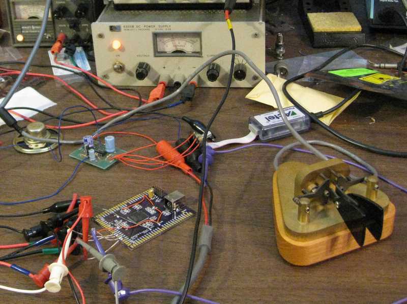
The iambic keyer core is alive

With just a few tweaks, I brought up the “IambicV” iambic keyer core on one of my A3PN250 breakout boards. I was stunned when it made dits, dahs, and iambic dah-dits perfectly the first time out. Yes, I know that’s what a testbench is supposed to make possible, and yes, I’ve had it happen before, but I still always expect smoke the first time I turn something on.

I made a few changes from last week’s version.

With just a few tweaks, I brought up the “IambicV” iambic keyer core on one of my A3PN250 breakout boards. I was stunned when it made dits, dahs, and iambic dah-dits perfectly the first time out. Yes, I know that’s what a testbench is supposed to make possible, and yes, I’ve had it happen before, but I still always expect smoke the first time I turn something on.

I made a few changes from last week’s version. One change was to invert the dit and dah pins. Although high-true logic is convenient within the keyer module, it seems like a good idea to have the actual paddles grounded, so the inputs had to be low-true. The physical constraints file enables the built-in pull-up resistors on the dit and dah pins.

For an audio amplifier, I used an old Saint Louis QRP Society LM380 board.

It’s all lashed together on my bench, but it works.

To download the core, see the iambic keyer project page.

Iambic keyer in Verilog

If my goal is to build an FPGA-based ham radio, one of the modules I can’t do without is an iambic keyer. I have to confess that I have never been much of a CW (Morse code) operator, but with so many logic gates available, it would be a shame to leave out a keyer.

Writing an iambic keyer turned out to be a good way to get the kinks out of the FPGA toolchain. The code itself is pretty simple and straightforward. One flip-flop keeps track of whether the current symbol is a dit or a dah. Another tracks whether the paddle for the opposite symbol (dah or dit, respectively) has been pressed during the current symbol. Finally, a two-level counter handles the timing of the dits and dahs and operates the key line. There is a simple sidetone, too.

If my goal is to build an FPGA-based ham radio, one of the modules I can’t do without is an iambic keyer. I have to confess that I have never been much of a CW (Morse code) operator, but with so many logic gates available, it would be a shame to leave out a keyer.

The basic idea behind an iambic keyer is to use a two-lever “paddle” to send Morse code. Pressing one paddle, usually with the thumb, sends a series of dits (dots), and pressing the other paddle, usually with the index finger, sends dahs (dashes). Squeezing both paddles alternates between dits and dahs. The didahdidahdidah… sound of squeezing the paddles sounds a bit like the iambic feet of English poetry, hence the name “iambic keyer”. If Shakespeare were a Morse code operator, one of his sonnets might include the sweet iambic pentameter “didahdidahdidah, didah didah!”

Writing an iambic keyer turned out to be a good way to get the kinks out of the FPGA toolchain. The code itself is pretty simple and straightforward. One flip-flop keeps track of whether the current symbol is a dit or a dah. Another tracks whether the paddle for the opposite symbol (dah or dit, respectively) has been pressed during the current symbol. Finally, a two-level counter handles the timing of the dits and dahs and operates the key line. There is a simple sidetone, too. Continue reading “Iambic keyer in Verilog”

The FPGA level shifter: not entirely crazy!

Some months ago, I came across an Actel app note that advocated using FPGAs as level shifters. “What a crazy waste of computing power,” I thought to myself, “though I suppose they are just trying to sell the low-end ProASIC3 nano FPGAs.” With that, I set the thought aside.

Much later, I ran into a problem.

Some months ago, I came across an Actel app note that advocated using FPGAs as level shifters. “What a crazy waste of computing power,” I thought to myself, “though I suppose they are just trying to sell the low-end ProASIC3 nano FPGAs.”  With that, I set the thought aside.

Much later, I ran into a problem. I had a prototype board to design. It had to plug into an existing, quite complicated microprocessor evaluation kit, adding a data radio and a few other functions to the system. After poring over the schematic for hours, the software developer, who I’ll call S, and I still weren’t 100% sure which pins on the expansion bus were free for our use, though we had a long list of pins that definitely were not suitable. On top of that, I had a level-shifting problem. The evaluation kit ran at 1.8 V and 2.75 V, with signals at both levels on the bus, but the radio required 3.3 V logic levels. Continue reading “The FPGA level shifter: not entirely crazy!”