Worst case design and the BITX 40 mic amp

The BITX 40’s microphone amp has a flaw that may shorten the lifespan of microphones by overstressing their components. Here’s what I found and how I fixed it so far.

Here’s the BITX 40 mic amp schematic:

The mic bias is supplied by the TX line through 4.9K of resistance. TX is the DC power supply, 12-15V.

Most electret microphones have a maximum voltage of 10 V, though I’ve seen a few datasheets with a 9 V limit. The data sheets also say that the mics draw 0.5 mA maximum. No minimum is given.

Now, applying Ohm’s law,

(0.5 \mathrm{mA}) * (4.9 \mathrm{k\Omega}) = 2.45 \mathrm{V}

Subtracting that from 12 V gives us 9.55 V, so one might think that everything is great.

Not really.

From the books of Bob Pease I learned the importance of worst case design. In worst case design, one looks at the datasheet minimum and maximum specifications and designs the circuit to work under the worst combination of specifications. Ignore the datasheet typical ratings, because those describe the best case. No one wants a circuit that only works in the best possible circumstances.

The BITX 40 docs specify a maximum power supply of 15 V, so that is the worst-case TX. The worst case microphone current is the minimum current, but I haven’t seen a mic datasheet that lists a minimum. Therefore, I have to make a guess. I need the guess to be on the safe side without being ridiculous. Knowing that the current is set by a JFET and knowing about both the variability of JFETs and how data sheet maximums are chosen, I could guess that the typical current is maybe half of the maximum and the minimum half of that, so 0.125 mA. If I want to make a truly robust circuit I could assume a minimum current of zero. I know a JFET can’t create current out of nothing, so the lowest possible current it draws is zero.

Let’s look at what voltages that creates:

(15 V) - (0.125 \mathrm{mA})(4.9 \mathrm{k\Omega}) = 14.388

Uh-oh. That’s well above the 10 V maximum for the mic.

The zero current case is easier to work out. With zero current through the resistor, the mic sees the full 15 V.

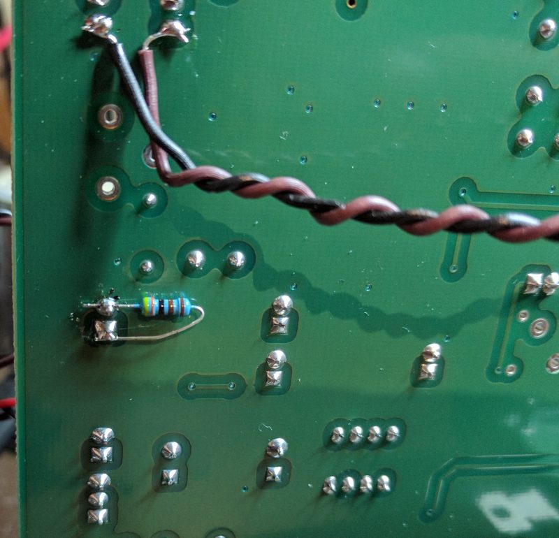
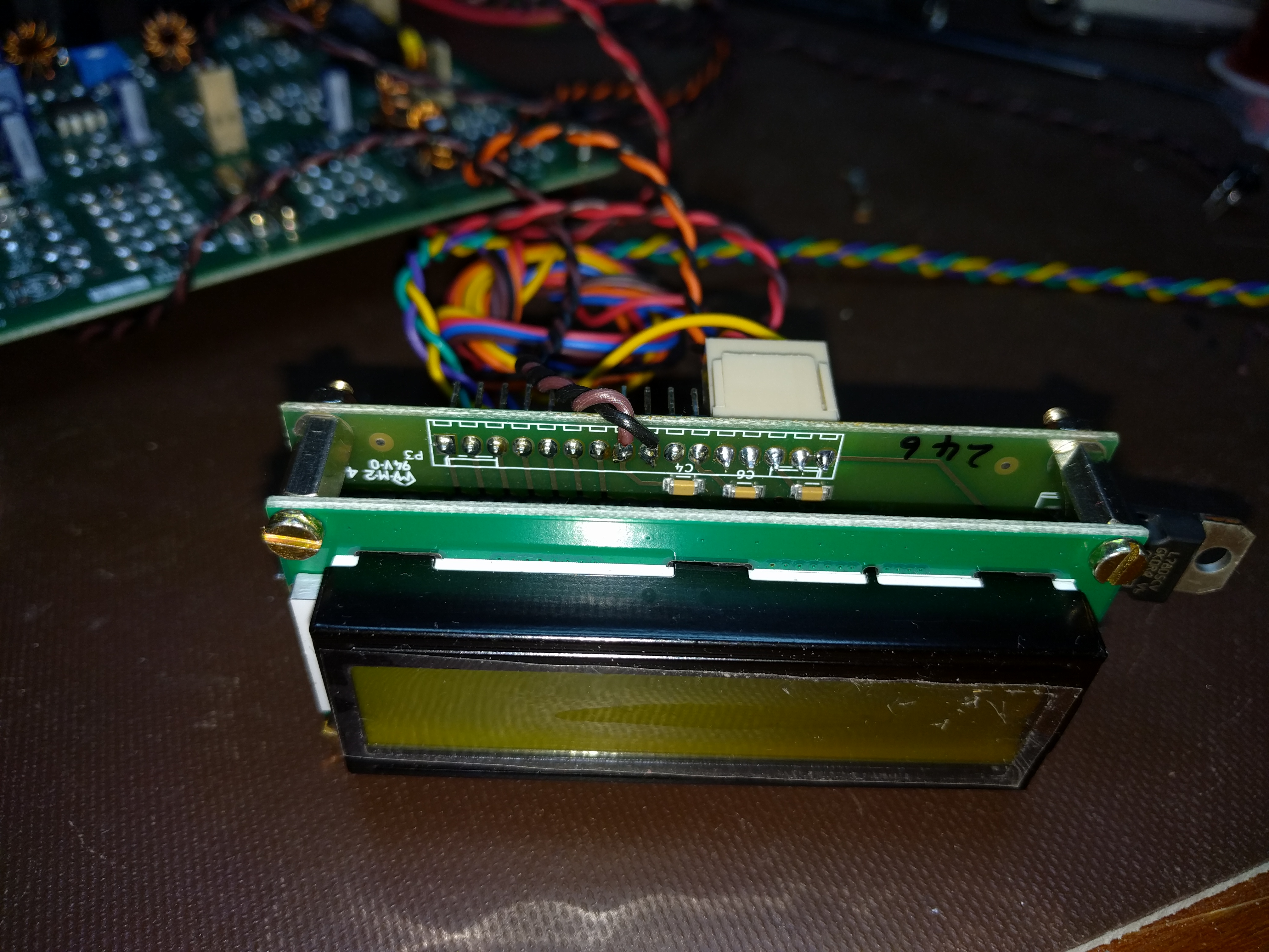
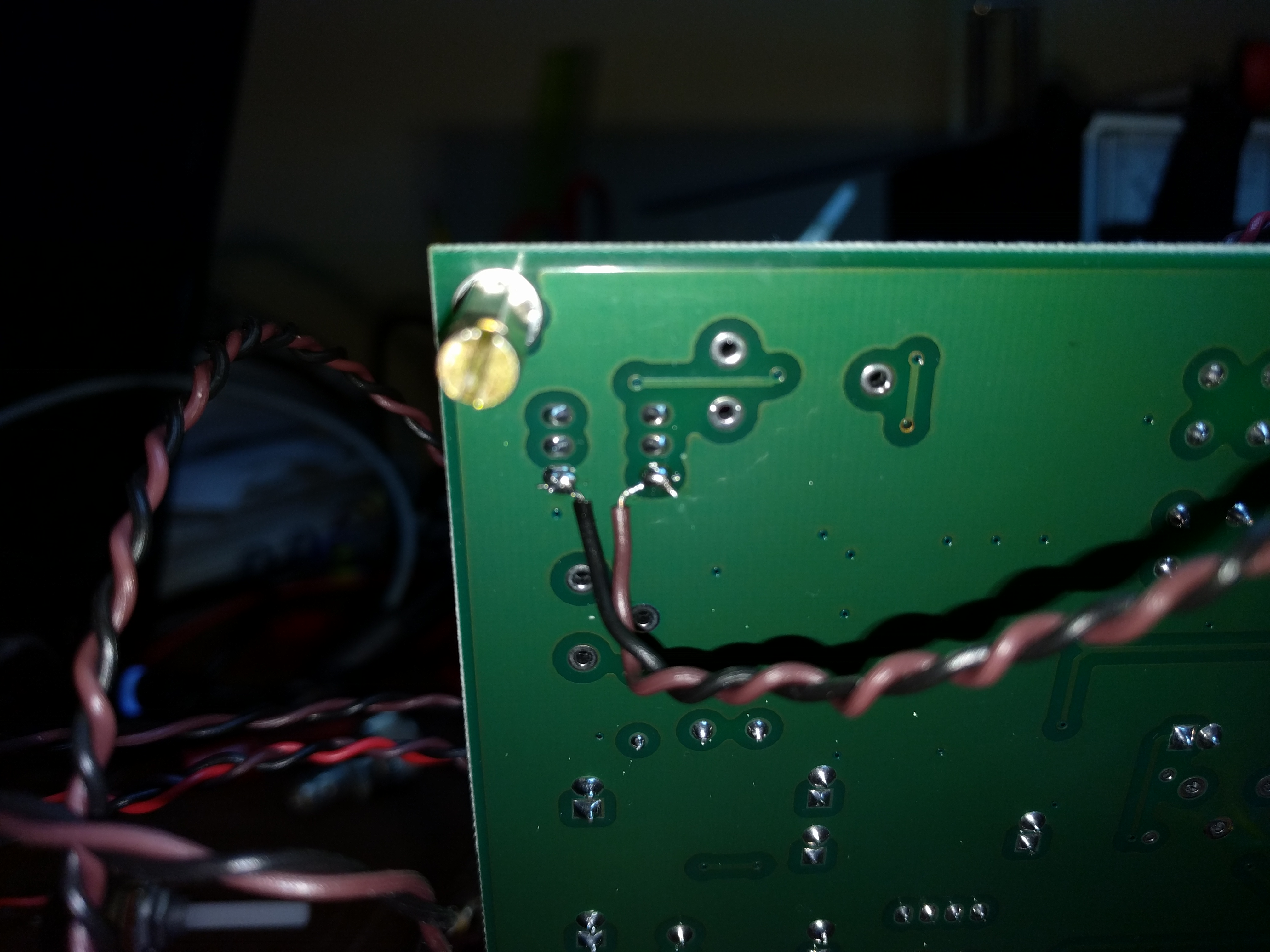
A simple fix is to put a resistor in parallel with MIC1, making a voltage divider. I use a computer headset with my BITX, and I know that computer mics are typically fed with 5 V through a 2.2 kΩ resistor. Knowing that, I picked a 4.3 kΩ resistor across MIC1 to form a voltage divider equivalent to 2.3 kΩ fed by 7 V. That’s close enough, and 7 V is well below the maximum for most electret elements.

Resistor location on the PCB.
The 4.3 kohm resistor on the underside of the BITX 40 PCB. The wires are for the Si5351 BFO mod I added.

Unfortunately, the mic now drives an impedance about 30% lower than before, reducing its output. The RF drive, R136, should be adjusted to compensate.

One could fix the issue a different way, of course. A Zener diode in series with R121 could drop the voltage just as effectively without lowering the amplifier’s input impedance. An LM780x regulator could do the job, too, albeit with more components. I happened to have 1% resistors within reach and Zener diodes on a different floor of the house. I chose the resistor.

Is this a real problem?

No one else seems to have noticed this issue, so it’s worth asking whether it matters. One answer is that it is worthwhile, and pleasing, to do things right. There is a place for bodging a circuit together that works as a one-off, but I enjoy the n-dimensional puzzle of getting the details right.

The other answer is that it might be killing microphones, but not often enough that anyone has noticed. The BITX 20 mailing list, home to BITX 40 discussion, has seen a few comments from hams whose microphone capsules worked for a while, then failed. Some have been able to trace the problems to bad solder joints or physical damage, but I have to wonder if any of the remaining unsolved cases were caused by overvoltage.

Manufacturer maximum specifications are based on an assumption about the device’s expected lifetime. Operating beyond that specification can be expected to shorten the device’s lifetime. Sometimes that shortened lifetime is dramatic, with a flash of light, a puff of smoke, or an outpouring of heat. Other times it is subtle and takes longer. Perhaps mic elements will fail faster than usual. Perhaps their average lifespan will be 2 years instead of 20.

The difference might not be enough to notice, but we can fix it anyway. Worst case design will save the day.

Replacing the BITX 40 BFO

The BITX 40 is all about modifications. The design itself is “cheap and cheerful”, and the circuit board is laid out to invite changes and experiments. I have a list of quirks I intend to fix in mine, and with that the mods began.

First up was a misalignment of the BFO. Each BITX 40 uses a set of 5 matched crystals, four for the IF filter and the fifth for the BFO. The BFO is set up to pull the crystal frequency slightly to put the audio passband in the right place, or at least it is supposed to. On mine, the BFO frequency was just inside the IF passband.

Having the BFO in the wrong place had several consequences. First, receive audio was bassy, running from about 0 Hz to 1800 Hz. This transmits audio frequencies that are not useful for communications and omits the ones around 2 kHz that are especially important. Worse, the passband actually stretch below 0 Hz, into the upper sideband, which meant that my transmitter was not suppressing the carrier. It was sending VSB, vestigial sideband, not SSB. That may be fine if you’re a TV transmitter, but it’s not the kind of clean SSB signal hams expect.

One solution, which Wayne NB6M used on his BITX 40, is to change the “pulling” capacitor in the BFO to put the frequency where it belongs. Instead, I replaced the BFO entirely with a spare channel on the Si5351 frequency synthesizer.

I started off by attaching wires to pins 8 and 9 of the Raduino board. These are Si5351 channel 0 and ground, respectively. For quick progress, I used a twisted pair. When I box it up, I will switch to coax and use a connector to make maintenance easier.

At the other end, I attached the wires to pins 1 and 6 of T4. This supplies the BFO to the second mixer.

Finally, I unsoldered R101 and C106 to remove power from the analog BFO and disconnect it from the second mixer.

With the hardware work done, I turned to the Arduino code. I downloaded Ashhar Farhan’s original bitx40 sketch and added one line of code near the bottom of setup().

si5351.set_freq(bfo_freq * 100ULL, SI5351_CLK0);

Then I turned it on, saw that the BFO was now too far above the IF passband, and with a couple of experiments, came up with the following edit near the top of the sketch:

#define INIT_BFO_FREQ (11997000L)
unsigned long baseTune = 7100000L;
unsigned long bfo_freq = INIT_BFO_FREQ;

With that, I was done. The rig sounds better and works better. I still haven’t transmitted, though. That will take one more mod which I will write about next.

BITX 40!

I’ve decided to build a BITX 40. This petite SSB transceiver sells for a mere $59, some assembly required. As it comes, it puts out approx. 7W, and with some straightforward upgrades it can produce 25W. It comes as a fully-assembled PCB plus most of the parts needed to hook it up. A case, speaker, and a few other incidentals are not included. The board and radio are designed to invite hacking and customization. It is also designed to serve as an introduction to homebrewing for hams who may not be ready to build a radio from scratch. For more information on the BITX-40, see its supplier http://www.hfsigs.com/ and the active and helpful support community at groups.io.

My BITX 40 is operable “al fresco” on my workbench. The included Arduino/Si5351 VFO works fine and tunes the full 40m band. It needs a little bit of work before I can transmit with it. It’s important to understand that the BITX 40 is not a turnkey rig. Many of them ship with small flaws, and figuring out and fixing the flaws is part of the fun. (This is why that helpful community at groups.io is so important.) Mine shares a flaw with Wayne, N6BM’s BITX 40 — the BFO frequency is inside the IF passband, instead of about 300 Hz below the passband like it should. This means that stations I tune sound bassy, I can hear part of the opposite sideband, and when I transmit, the carrier is not suppressed.

(I suppose I could call it “vestigial sideband”, like what NTSC TV uses, but it’s supposed to be SSB…)

Wayne fixed the problem by changing a capacitor in the BFO circuit to pull the frequency where it needed to be. I plan to fix it by disabling the analog BFO and instead use a spare Si5351 output. Having a tunable VFO will let me put the passband exactly where I want. With a little more code, it will also give me passband tuning.

I think I found a bug in the microphone amp that I’m going to take a closer look at, and I found a perfect case at the Mike and Key hamfest in Puyallup last month. I didn’t even try to negotiate the price. It was free!

I’ll have more on my BITX 40 project in upcoming posts.

Antenna in the air

I finally have an antenna in the air. After a lot of thought about the shape of our lot, the placement of trees, and how to avoid obstructing my children’s use of the yard, I settled on an end-fed halfwave, the LNR Precision EF-10/20/40 Mk II.

The main challenge of the installation was minimizing the ground area obstructed. I have two small children who like to run and play, so guy lines spanning the yard is out of the question. Similarly, I don’t want to set up an inverted-V anchored at the ground. I solved the problem by sloping it between two trees. The high end hangs about 40 feet up from a cedar, and the low end is 8 feet up in a pine. (It’s not for nothing that Washington is the Evergreen State.) Both are right by our property lines, so the entire assembly, including the feed line, are out of the way.

I tuned it with a signal generator and my trusty Oak Hills Research QRP power meter. The SWR bandwidth is broader than I expected. I’ll see how it holds up with higher power output — it’s always possible my generator’s output is too low for an accurate reading.

I can’t wait to try it on the air.

The Sound-Following Robot

“What do you want to get Nick for Christmas?” “A robot!” My daughter was adamant that her big brother needed a robot for Christmas. I hit the ‘net, and found many robots. I wanted to give him something that actually worked, that was educational, and that was affordable. Because watching Dad solder is no fun, I also ruled out anything that required soldering. That narrowed it down to two choices. “Which one do you want to give to Nick, Sally?” I asked, and started to explain their relative merits. “THE BLUE ONE!” And so it was decided that Nick and I would build an Elenco Sound-Following Robot. IMG_6375 
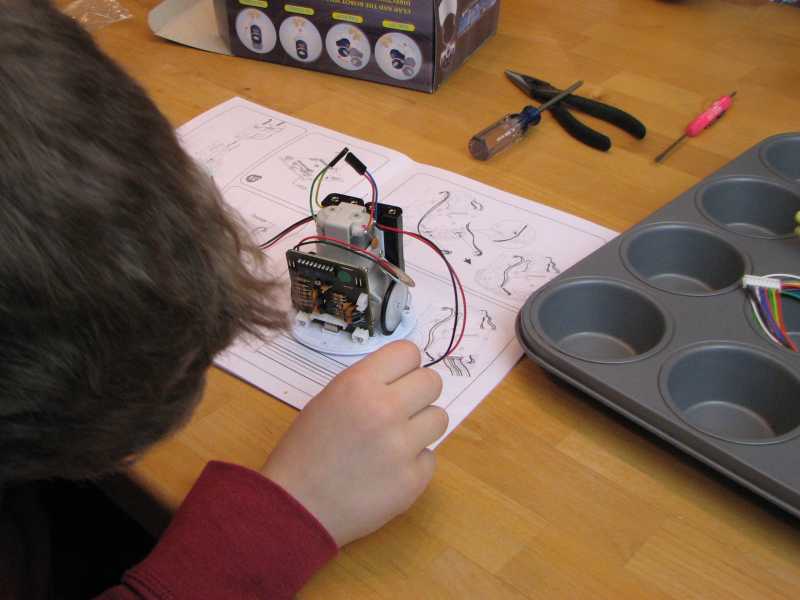
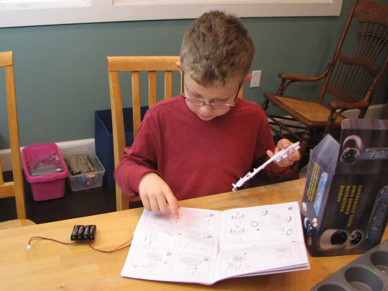
The kit is marketed for kids 13 and up. Nick is still in kindergarten, but loves anything motorized or electronic, so we did it together. The manual used exploded assembly diagrams to show how the pieces went together. Few words are used, and some skill in interpreting drawings is helpful in figuring out the steps. In other words, this was very much a collaborative effort for us. I figured out what went where, he found the parts, and we jointly did the assembly. Though one could probably do the project alone, there certainly were times when it helped to have four hands.IMG_6378 
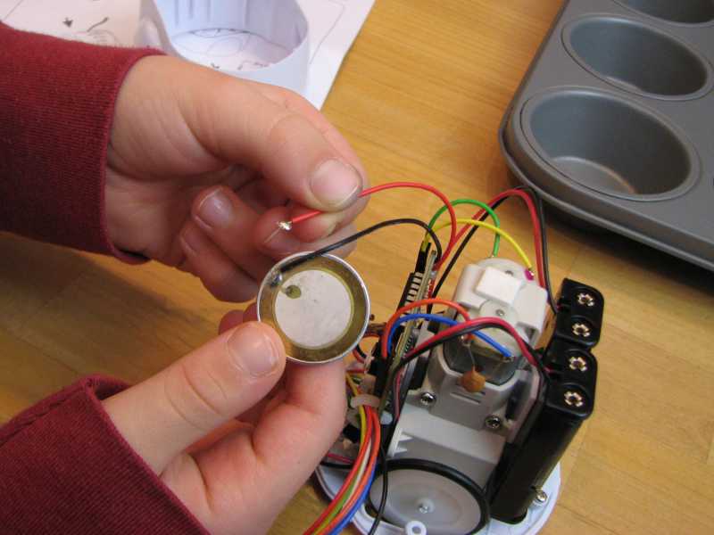
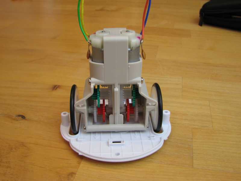
The robot is built around a drive train, the pieces for which are separately bagged. This suggests it’s common to other robot kits. Though the assembly instructions were clear, the gears were fiddly to assemble. At one point, we managed to undo almost all of our previous work when we tried to slip the last gear onto its shaft. No matter; we were able to put it back together. At this point in the assembly, with a drivetrain and a bottom plate, the possibilities of hacking this robot became clear. IMG_6383 
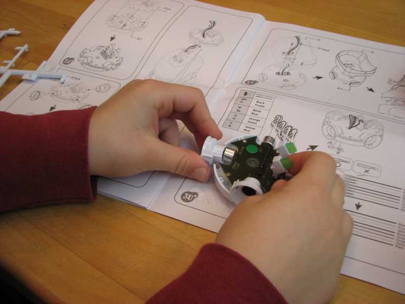
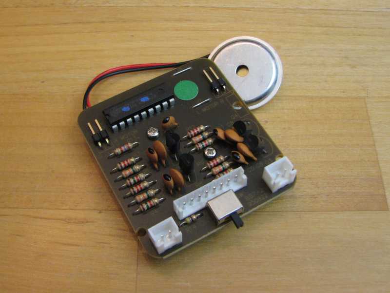
The controller for the robot comes preassembled. The IC on top of the board is a microcontroller. It is house-labelled for Elenco, but I suspect it’s a standard part with custom firmware. The manual has a schematic, so I compared the pinout to PICs and AVRs without finding a match. Maybe it’s a 68HC05 or another small micro. The assembly drawing pictured a socket under the microcontroller, but no such luck on this production unit. (By this time, I was started to get intrigued by the modification possibilities for this little robot.) IMG_6387

We ran into our first glitch when a lead broke off of the speaker. A trip to Radio Shack turned up another speaker that could be trimmed to fit.

IMG_6390

The “head” of the robot has its own PCB ringed by four microphones to detect sound. Two LEDs serve as “eyes” and give feedback on the direction of sound detected by the robot.

IMG_6394

That’s one happy boy playing with his new robot. His mother is a little less excited about it. A sound-following robot likes it noisy. Clap! Clap! Clap! Clap! Clap! Clap! Clap! Clap! Clap! Clap! Clap! Clap! Clap! Clap! Clap! Clap! Clap! Clap! Clap! Clap! Clap! Clap! Clap! Clap! Clap! Clap! Clap! Clap! Clap! Clap! Clap! Clap! Clap! Clap! Clap! Clap! Clap! Clap! Clap! Clap! Clap! Clap! Clap! Clap! Clap! Clap! Clap! Clap! Clap! Clap! Clap! Clap! Clap! Clap! Clap! Clap! Clap! Clap! Clap! Clap! Clap! Clap! Clap! Clap! Clap! Clap! Clap! Clap! Clap! Clap! Clap! Clap! ….

IMG_6396

pQRP

Last night I attended a very enjoyable gathering of the Pacific Northwest QRP (pQRP) group. I’ve been wishing for some time to find a group of like-minded hams. Like-minded, that is, in the sense that they are interested in design and building as well as operation. Imagine my pleasure at hearing from not one, but four hams involved in design projects as well as others enjoying the experimental side of the hobby, even down to one gentleman who is testing an add-on heat sink for his Elecraft KX-3.

Several members of the club are involved in designing and building a variant of Ashhar Farhan’s “Minima” transceiver. They are equipping it with Si570 oscillators and a comfortable user interface, while trying to stay close to the original spirit of the radio. A potentiometer is still the interface for frequency control, for example, instead of a rotary encoder.

Other members of the club are active in operating, including SOTA, RTTY contests, and other pursuits.

As show and tell, I brought along my NorCal 40A, which neither tunes as widely as it should nor outputs full power. So far it has stumped me. The consensus of the group was to post about it to the club mailing list and see who has some ideas to try.

I’m already looking forward to next month’s meeting.

Digging up a Dinosaur – a Boatanchor at the Children’s Museum

Last weekend, I took my children to the Imagine Children’s Museum in Everett, WA. On the roof, my daughter found this National NC-173 as part of a “dinosaur dig” exhibit. It may have been gutted. At the very least, the controls are certainly not original! The colorful, kid-resistant buttons cause a speaker to play a variety of recorded messages, supposedly radio communications with a base camp.

It has been painted so many times, I could hardly identify it. Through the paint, I found an engraved “80”, “40”, and “10-20” by what may have been a band switch. Peering harder, I could just make out the model number.

I’m not a boatanchor guy, and some might bemoan the loss of a historic radio. It made me smile to find it, though, and my daughter enjoyed playing with it. That’s enough for me.

image


When I brought my children to the Imagine Children’s Museum (Everett, WA) last weekend, they showed me the “dinosaur dig” exhibit on the roof. There we found this National NC-173 receiver, of Kon-Tiki fame. It looks like it has been gutted. The controls certainly aren’t original. The brightly-colored, kid-resistant buttons cause it to play recorded messages from a “base camp” to the pretend-paleontologists at the dig.

I had to peer through layers of paint to read the engravings and identify it. The best remaining marking is “80”, “40”, and “10-20” by what may have been a band switch. I could barely find the model number under all the paint.

I’m not a boatanchor guy, and I understand that some might bemoan the loss of a classic receiver. My daughter enjoyed playing with it, though, and it made me smile to find it, so it’s all right with me.