Worst case design and the BITX 40 mic amp

The BITX 40’s microphone amp has a flaw that may shorten the lifespan of microphones by overstressing their components. Here’s what I found and how I fixed it so far.

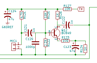
Here’s the BITX 40 mic amp schematic:

The mic bias is supplied by the TX line through 4.9K of resistance. TX is the DC power supply, 12-15V.

Most electret microphones have a maximum voltage of 10 V, though I’ve seen a few datasheets with a 9 V limit. The data sheets also say that the mics draw 0.5 mA maximum. No minimum is given.

Now, applying Ohm’s law,

(0.5 \mathrm{mA}) * (4.9 \mathrm{k\Omega}) = 2.45 \mathrm{V}

Subtracting that from 12 V gives us 9.55 V, so one might think that everything is great.

Not really.

From the books of Bob Pease I learned the importance of worst case design. In worst case design, one looks at the datasheet minimum and maximum specifications and designs the circuit to work under the worst combination of specifications. Ignore the datasheet typical ratings, because those describe the best case. No one wants a circuit that only works in the best possible circumstances.

The BITX 40 docs specify a maximum power supply of 15 V, so that is the worst-case TX. The worst case microphone current is the minimum current, but I haven’t seen a mic datasheet that lists a minimum. Therefore, I have to make a guess. I need the guess to be on the safe side without being ridiculous. Knowing that the current is set by a JFET and knowing about both the variability of JFETs and how data sheet maximums are chosen, I could guess that the typical current is maybe half of the maximum and the minimum half of that, so 0.125 mA. If I want to make a truly robust circuit I could assume a minimum current of zero. I know a JFET can’t create current out of nothing, so the lowest possible current it draws is zero.

Let’s look at what voltages that creates:

(15 V) - (0.125 \mathrm{mA})(4.9 \mathrm{k\Omega}) = 14.388

Uh-oh. That’s well above the 10 V maximum for the mic.

The zero current case is easier to work out. With zero current through the resistor, the mic sees the full 15 V.

A simple fix is to put a resistor in parallel with MIC1, making a voltage divider. I use a computer headset with my BITX, and I know that computer mics are typically fed with 5 V through a 2.2 kΩ resistor. Knowing that, I picked a 4.3 kΩ resistor across MIC1 to form a voltage divider equivalent to 2.3 kΩ fed by 7 V. That’s close enough, and 7 V is well below the maximum for most electret elements.
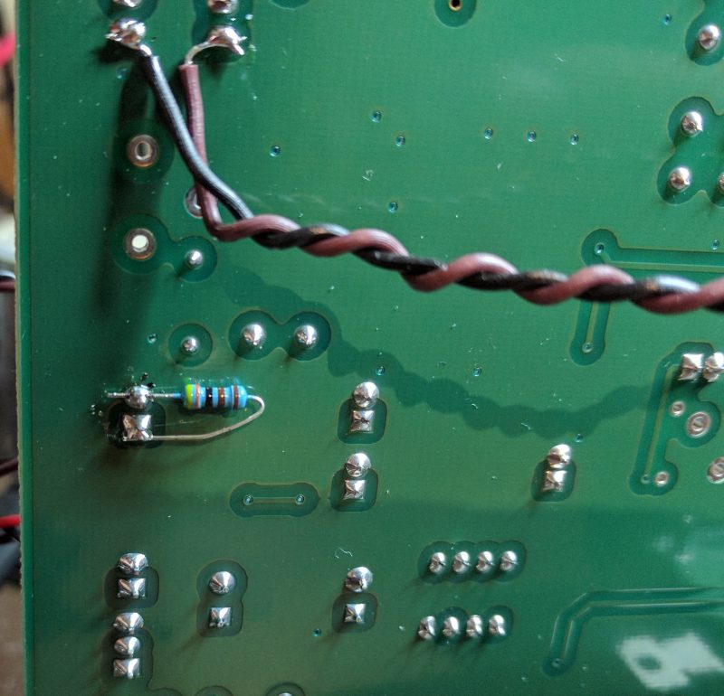
Resistor location on the PCB.
The 4.3 kohm resistor on the underside of the BITX 40 PCB. The wires are for the Si5351 BFO mod I added.

Unfortunately, the mic now drives an impedance about 30% lower than before, reducing its output. The RF drive, R136, should be adjusted to compensate.

One could fix the issue a different way, of course. A Zener diode in series with R121 could drop the voltage just as effectively without lowering the amplifier’s input impedance. An LM780x regulator could do the job, too, albeit with more components. I happened to have 1% resistors within reach and Zener diodes on a different floor of the house. I chose the resistor.

Is this a real problem?

No one else seems to have noticed this issue, so it’s worth asking whether it matters. One answer is that it is worthwhile, and pleasing, to do things right. There is a place for bodging a circuit together that works as a one-off, but I enjoy the n-dimensional puzzle of getting the details right.

The other answer is that it might be killing microphones, but not often enough that anyone has noticed. The BITX 20 mailing list, home to BITX 40 discussion, has seen a few comments from hams whose microphone capsules worked for a while, then failed. Some have been able to trace the problems to bad solder joints or physical damage, but I have to wonder if any of the remaining unsolved cases were caused by overvoltage.

Manufacturer maximum specifications are based on an assumption about the device’s expected lifetime. Operating beyond that specification can be expected to shorten the device’s lifetime. Sometimes that shortened lifetime is dramatic, with a flash of light, a puff of smoke, or an outpouring of heat. Other times it is subtle and takes longer. Perhaps mic elements will fail faster than usual. Perhaps their average lifespan will be 2 years instead of 20.

The difference might not be enough to notice, but we can fix it anyway. Worst case design will save the day.
Cool chip: LT1970 power op amp with current limit

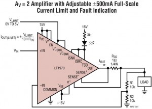
LT1970 power op amp configured for a gain of two and a variable current limit inputThis week I want to share a new favorite chip of mine, the LT1970 power op amp from Linear Technology. This nifty device runs from a 36 V supply and can source or sink 500 mA. That’s not too unusual, but how about programmable current limiting, outputs to indicate over-temperature and over-current, and more? Think of it as a four-quadrant power supply on a chip, or as the source part of a source measurement unit.

The first nice feature of the chip is the programmable current limit. The chip has two inputs, one for sourced current and one for sunk current, that accept a voltage from 0 V to 5 V. It compares these voltages against the current measured across an external sense resistor and limits its output when the measured current exceeds 1/10 the voltage on the relevant control pin. Differential input pins, independent of the output pin, are provided for the sense resistor.

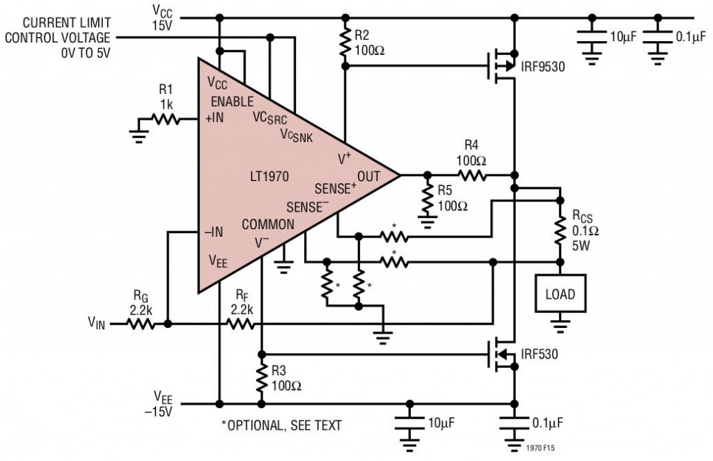
Another great feature is that the output stage has its own power pins. One of the neater “trick” circuits out there is to boost the current capability of an op amp by using the power supply pins to drive external transistors. An ordinary op amp without separate power pins can also be used this way, but the bias current of the external transistors will be proportional to the op amp’s quiescent current, which means one will probably need a low quiescent current model. By pinning out the output stage’s power pins, the LT1970 makes it easier.

This circuit ends up running the output transistors in class AB. The bias current in the transistors is controlled, in part, by the quiescent current of the op amp. When the op amp tries to increase the voltage of its output, it will deliver more current to the output, pulling that current from its power supply. That, in turn, changes the voltage on the base of the upper external MOSFET, causing it to source more current as well. The equivalent happens when the op amp needs to sink current.

Another advantage of choosing the LT1970 for this configuration, instead of an ordinary op amp, is that all stages except the output stage will see a stable power supply, keeping the PSRR up where it belongs. As for the last stage, when combined with the external transistors, it resembles two Sziklai pairs (also called “complementary Darlingtons”) biased into class AB.

The separate power pins also make it easy to use a lower-noise supply for the input stages and a high-current supply for the output. I used them for another purpose: My application needed a wide input range but drove an input sensitive to overvoltage. Running the input stages off of 24V and the output stage from a lower voltage ensures the output will not hit an unsafe value. Watch out, though, because V+ and V- must be within the VCC and VEE supplies to the op amp’s input stages.

Another neat feature is three open-collector outputs that indicate that the op amp has gone into thermal limiting, into current source limiting, or into current sink limiting. These pins can drive LEDs for an easy status display.

The biggest drawback of the LT1970 is its package, a 20-pin TSSOP with a thermal pad on the bottom. That thermal pad means you pretty much have to have either a hot air or reflow setup to solder it.

As you might expect for a part like this, there are ways to use it beyond the obvious. The current-limiting flag outputs can be used for snap-back current limiting, where the output current is sharply reduced after it enters limiting. The current sense pins can be used as voltage-limit inputs, enabling circuits like a symmetric, voltage-controlled limiter. These ideas are from the data sheet; I haven’t tried my creativity at coming up with other ways to (ab)use the chip.

No, I used the chip for a boring old power supply. It was a two-quadrant supply, though, meaning (in this case) that I needed a positive-output power supply that would either source or sink current to maintain its output voltage. The voltage was controlled by an analog input. What I needed was basically just an op amp with current limits and a few hundred milliamps output. The LT1970 was perfect. I fitted it with potentiometers to adjust the current limits, a set of LEDs for the status outputs, and as much PCB copper as I could manage for a heat spreader. I also included some compensation for capacitive loads. It worked great. I haven’t had any issues with oscillation, the LEDs have been handy to tell me when I mess up, and the current limit has saved my bacon at least once. Sure, I could have built the same supply from separate parts for a lower cost, but it would not have been nearly as easy or as quick. This is another case where it was worth spending a little money on a chip in exchange for saving a little engineering time.

The feature I miss most from the LT1970 is a current amplifier output. It does current measurement internally, for the current limit feature, but a voltage proportional to current is not brought out. For my power supply, I had to add an external difference amplifier to measure the output current. The difference amp used the same current sense resistor as the LT1970, but it would have been nice to have that function built in.

The quantity 1 price for the LT1970 is $9.88 from Digi-Key or $6.05 directly from Linear Technology.

Figures: Copyright 2002 Linear Technology Corporation. Used by permission.

SiliconBlue ultra-low-power FPGAs

Some time ago, I wrote, “The Actel/Microsemi parts have one additional advantage: They have the best static power consumption in the industry.”  I was wrong.

Last month, a post on the geda-user mailing list alerted me to SiliconBlue Technologies and their line of ultra-low-power FPGAs. These FPGAs are RAM-based, like those of the big two FPGA manufacturers, Xlinix and Altera. Unlike the chips from the big guys, though, SiliconBlue’s parts are not power hogs. In fact, they are fully static and go down to microamps with a static clock.  With the Microsemi (Actel) FPGAs, one has to freeze the FPGA with the “Flash Freeze” feature to get down to that level, but it appears that the SiliconBlue units simply clock right down there.  If true, that would give them quite an edge in power-conscious design.

Making a direct comparison between the Actel/Microsemi Igloo line, their lowest-powered, and the SiliconBlue parts has to be done on a case-by-case basis. The clock rates, and in particular, how often the clocks can be stopped, matter a lot. There is also the external configuration EEPROM for the Silicon Blue parts, which will take power in simple designs, but can be powered down or perhaps eliminated in more sophisticated uses.

In any event, I will stick with the Microsemi ProASIC3 and Igloo line for now. I like the convenience of a flash-based architecture. The next time I’m designing for low power, though,  it will be time to give SiliconBlue a good look.

Updated 5/12/11: The date of the geda-user post was corrected.

Freescale’s SDR on a Chip

Freescale has introduced a very nifty part, the MC13260 SoC Radio, where SoC is “System on a Chip”.  Picture for a moment a complete transceiver on a chip, including an 100 MHz ARM processor, a programmable DSP modem, a frequency synthesizer, a transceiver, a USB interface, an audio CODEC (for the microphone and speaker), and miscellaneous support components, all on one chip.

The thing operates at RF frequencies from 60 to 960 MHz. It’s designed primarily for analog FM and certain digital modes, but with an external modulator it can support linear modes, presumably including SSB.  Output is only 5 dBm, so the advertised “few external components” had better include an amplifier!

Though the chip is aimed at the military and commercial markets, hypothetically it could make the fine foundation for a fine amateur transceiver for any or all of the 2m, 1.25m, 70cm, or 33cm bands. Imagine an all-mode 2m, software defined radio HT with built-in data capabilities, for example. Integrated parts like this usually can’t achieve the performance of a discrete design, but the reduced part count would be worth the tradeoff.

What do you think? Would a transceiver based on a part like this be within the reach of a few dedicated homebrewers?

Freescale MC13260 data / article in Electronic Design