Worst case design and the BITX 40 mic amp

The BITX 40’s microphone amp has a flaw that may shorten the lifespan of microphones by overstressing their components. Here’s what I found and how I fixed it so far.

Here’s the BITX 40 mic amp schematic:

The mic bias is supplied by the TX line through 4.9K of resistance. TX is the DC power supply, 12-15V.

Most electret microphones have a maximum voltage of 10 V, though I’ve seen a few datasheets with a 9 V limit. The data sheets also say that the mics draw 0.5 mA maximum. No minimum is given.

Now, applying Ohm’s law,

(0.5 \mathrm{mA}) * (4.9 \mathrm{k\Omega}) = 2.45 \mathrm{V}

Subtracting that from 12 V gives us 9.55 V, so one might think that everything is great.

Not really.

From the books of Bob Pease I learned the importance of worst case design. In worst case design, one looks at the datasheet minimum and maximum specifications and designs the circuit to work under the worst combination of specifications. Ignore the datasheet typical ratings, because those describe the best case. No one wants a circuit that only works in the best possible circumstances.

The BITX 40 docs specify a maximum power supply of 15 V, so that is the worst-case TX. The worst case microphone current is the minimum current, but I haven’t seen a mic datasheet that lists a minimum. Therefore, I have to make a guess. I need the guess to be on the safe side without being ridiculous. Knowing that the current is set by a JFET and knowing about both the variability of JFETs and how data sheet maximums are chosen, I could guess that the typical current is maybe half of the maximum and the minimum half of that, so 0.125 mA. If I want to make a truly robust circuit I could assume a minimum current of zero. I know a JFET can’t create current out of nothing, so the lowest possible current it draws is zero.

Let’s look at what voltages that creates:

(15 V) - (0.125 \mathrm{mA})(4.9 \mathrm{k\Omega}) = 14.388

Uh-oh. That’s well above the 10 V maximum for the mic.

The zero current case is easier to work out. With zero current through the resistor, the mic sees the full 15 V.

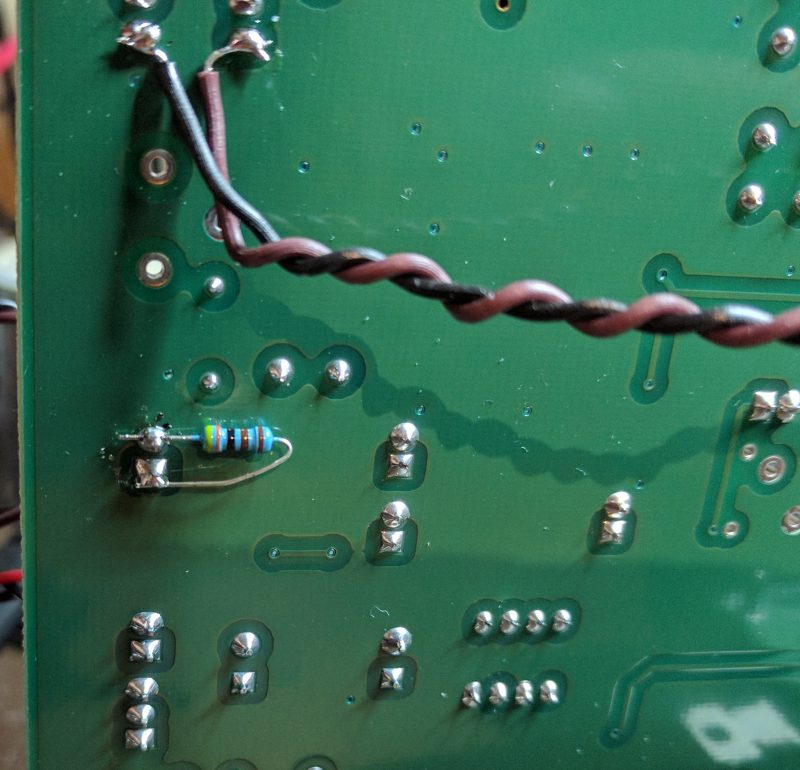
A simple fix is to put a resistor in parallel with MIC1, making a voltage divider. I use a computer headset with my BITX, and I know that computer mics are typically fed with 5 V through a 2.2 kΩ resistor. Knowing that, I picked a 4.3 kΩ resistor across MIC1 to form a voltage divider equivalent to 2.3 kΩ fed by 7 V. That’s close enough, and 7 V is well below the maximum for most electret elements.

Resistor location on the PCB.
The 4.3 kohm resistor on the underside of the BITX 40 PCB. The wires are for the Si5351 BFO mod I added.

Unfortunately, the mic now drives an impedance about 30% lower than before, reducing its output. The RF drive, R136, should be adjusted to compensate.

One could fix the issue a different way, of course. A Zener diode in series with R121 could drop the voltage just as effectively without lowering the amplifier’s input impedance. An LM780x regulator could do the job, too, albeit with more components. I happened to have 1% resistors within reach and Zener diodes on a different floor of the house. I chose the resistor.

Is this a real problem?

No one else seems to have noticed this issue, so it’s worth asking whether it matters. One answer is that it is worthwhile, and pleasing, to do things right. There is a place for bodging a circuit together that works as a one-off, but I enjoy the n-dimensional puzzle of getting the details right.

The other answer is that it might be killing microphones, but not often enough that anyone has noticed. The BITX 20 mailing list, home to BITX 40 discussion, has seen a few comments from hams whose microphone capsules worked for a while, then failed. Some have been able to trace the problems to bad solder joints or physical damage, but I have to wonder if any of the remaining unsolved cases were caused by overvoltage.

Manufacturer maximum specifications are based on an assumption about the device’s expected lifetime. Operating beyond that specification can be expected to shorten the device’s lifetime. Sometimes that shortened lifetime is dramatic, with a flash of light, a puff of smoke, or an outpouring of heat. Other times it is subtle and takes longer. Perhaps mic elements will fail faster than usual. Perhaps their average lifespan will be 2 years instead of 20.

The difference might not be enough to notice, but we can fix it anyway. Worst case design will save the day.

Replacing the BITX 40 BFO

The BITX 40 is all about modifications. The design itself is “cheap and cheerful”, and the circuit board is laid out to invite changes and experiments. I have a list of quirks I intend to fix in mine, and with that the mods began.

First up was a misalignment of the BFO. Each BITX 40 uses a set of 5 matched crystals, four for the IF filter and the fifth for the BFO. The BFO is set up to pull the crystal frequency slightly to put the audio passband in the right place, or at least it is supposed to. On mine, the BFO frequency was just inside the IF passband.

Having the BFO in the wrong place had several consequences. First, receive audio was bassy, running from about 0 Hz to 1800 Hz. This transmits audio frequencies that are not useful for communications and omits the ones around 2 kHz that are especially important. Worse, the passband actually stretch below 0 Hz, into the upper sideband, which meant that my transmitter was not suppressing the carrier. It was sending VSB, vestigial sideband, not SSB. That may be fine if you’re a TV transmitter, but it’s not the kind of clean SSB signal hams expect.

One solution, which Wayne NB6M used on his BITX 40, is to change the “pulling” capacitor in the BFO to put the frequency where it belongs. Instead, I replaced the BFO entirely with a spare channel on the Si5351 frequency synthesizer.

I started off by attaching wires to pins 8 and 9 of the Raduino board. These are Si5351 channel 0 and ground, respectively. For quick progress, I used a twisted pair. When I box it up, I will switch to coax and use a connector to make maintenance easier.

At the other end, I attached the wires to pins 1 and 6 of T4. This supplies the BFO to the second mixer.

Finally, I unsoldered R101 and C106 to remove power from the analog BFO and disconnect it from the second mixer.

With the hardware work done, I turned to the Arduino code. I downloaded Ashhar Farhan’s original bitx40 sketch and added one line of code near the bottom of setup().

si5351.set_freq(bfo_freq * 100ULL, SI5351_CLK0);

Then I turned it on, saw that the BFO was now too far above the IF passband, and with a couple of experiments, came up with the following edit near the top of the sketch:

#define INIT_BFO_FREQ (11997000L)
unsigned long baseTune = 7100000L;
unsigned long bfo_freq = INIT_BFO_FREQ;

With that, I was done. The rig sounds better and works better. I still haven’t transmitted, though. That will take one more mod which I will write about next.

BITX 40!

I’ve decided to build a BITX 40. This petite SSB transceiver sells for a mere $59, some assembly required. As it comes, it puts out approx. 7W, and with some straightforward upgrades it can produce 25W. It comes as a fully-assembled PCB plus most of the parts needed to hook it up. A case, speaker, and a few other incidentals are not included. The board and radio are designed to invite hacking and customization. It is also designed to serve as an introduction to homebrewing for hams who may not be ready to build a radio from scratch. For more information on the BITX-40, see its supplier http://www.hfsigs.com/ and the active and helpful support community at groups.io.

My BITX 40 is operable “al fresco” on my workbench. The included Arduino/Si5351 VFO works fine and tunes the full 40m band. It needs a little bit of work before I can transmit with it. It’s important to understand that the BITX 40 is not a turnkey rig. Many of them ship with small flaws, and figuring out and fixing the flaws is part of the fun. (This is why that helpful community at groups.io is so important.) Mine shares a flaw with Wayne, N6BM’s BITX 40 — the BFO frequency is inside the IF passband, instead of about 300 Hz below the passband like it should. This means that stations I tune sound bassy, I can hear part of the opposite sideband, and when I transmit, the carrier is not suppressed.

(I suppose I could call it “vestigial sideband”, like what NTSC TV uses, but it’s supposed to be SSB…)

Wayne fixed the problem by changing a capacitor in the BFO circuit to pull the frequency where it needed to be. I plan to fix it by disabling the analog BFO and instead use a spare Si5351 output. Having a tunable VFO will let me put the passband exactly where I want. With a little more code, it will also give me passband tuning.

I think I found a bug in the microphone amp that I’m going to take a closer look at, and I found a perfect case at the Mike and Key hamfest in Puyallup last month. I didn’t even try to negotiate the price. It was free!

I’ll have more on my BITX 40 project in upcoming posts.

Some thoughts on the K5BCQ Si570 signal source

For the last few months, I’ve been working on building a radio from a pair of kits old enough to vote: KK7B’s R2 receiver and T2 transmitter. A complete transceiver built from these kits needs some other pieces, including a VFO (variable frequency oscillator). After looking around a bit, I picked an Si570 signal source kit from Kees Talen K5BCQ and John Fisher K5JHF.

Si570 signal source and frequency counter, showing 17 Hz difference at 10 MHz

I’m not going to try to review the kit, because Jack Smith wrote the canonical review of it already. Instead, I will share some impressions of the kit.

First off, the PCB layout has not gotten better. There are some crazy things about it, including through-hole parts mounted on opposite sides of the board, such that one component prevents access to the terminals for another. The layout of the output circuit is also odd. In an effort to provide for many different output options, apparently while keeping trace lengths to a minimum, the output section is crowded and hard to navigate.

I had to do only a little debugging after assembly. The first problem was that the two pads at the ends of the Si570 were not well-soldered. Jack Smith ran into the same problem. My second problem was a little more subtle. I fired up the circuit and saw output at the right frequency, but 0.5 V in amplitude. I purchased the CMOS output option, so it should have been a 3.3 V square wave. Tracing out the circuit, I found that the signal was getting knocked down when it passed through a DC blocking capacitor. Oddly enough, I noticed that when my ‘scope probe pushed down on the right spot on the capacitor, the output jumped up to 3.3 V. I probably fractured the cap with the heat of soldering. I had changed my mind about capacitive coupling anyway, so I replaced the cap with a 0 ohm resistor and now I get the output I expect.

Waveform from the Si570 VFO

The ‘scope shot shows the output, which is a reasonably clean 3.3 V CMOS signal. There is almost a volt of overshoot on the transitions, which is a little concerning, but I am not too worried about it at this point. The CMOS edges are fast, making overshoot understandable, and the size of the overshoot is likely to change as the VFO is integrated into the radio. I will worry about it later.

All in all, I have to say that the board works a treat. It is awesome to see 1 Hz tuning resolution and crystal oscillator stability coming out of a tiny 8-pin surface-mount part. I measured the frequency as being off by about 14 to 17 Hz at 10 MHz, which works out to about 1.7 ppm. Drift is confined to that 3 Hz range, at least when sitting on my basement workbench. The board does have a provision to calibrate out the frequency error, which I have not used yet. This much error really doesn’t matter.

The microcontroller firmware with the kit works well. The user interface is slightly unusual, with a decimal point used as an input cursor, but it works fine in practice. I do wish there was a way to configure band limits. The board has provisions for band selection, with up to eight bands possible. However, regardless of the band selection, the device will tune over its entire range. In a multi-band radio that is a poor idea, because it would be too easy to transmit at the wrong frequency and damage the final amplifier. With hundreds of on-board memories (100 per band, minus 20 reserved for setup), it would be nice if a few configuration memories were used to choose tuning limits for each band.

Over all I am happy with the board. It will serve just fine as my VFO.

Working slowly on the R2/T2 radio

I was at my workbench when my son came downstairs to talk and hang out. A budding reader, he soon started singing the A-B-C song with the letters mixed up. It crossed my mind that this was odd, but I didn’t think much about it until I heard

That rang a bell, and suddenly I realized he was singing my oscilloscope’s front panel. Music by Mother Goose, lyrics by Tektronix.

When he came downstairs, I was working on assembling the K5JHF/K5BCQ Si570 synthesizer kit. It turned out to be a bit fiddly, but it is a decent kit. That said, I would not lay out a PCB like this one. It has a number of vias in the middle of pads, and while that’s not a big problem for hand-soldering, I would avoid it in a PCB as a matter of good practice. You never know who might decide to use solder paste and reflow to assemble the board, and then those vias will be trouble.

Worse, though, is the positioning of the connector for the LCD. It is laid out smack in the middle of the footprint for the microcontroller, but on the opposite side of the board. If you look at the big black socket in the picture above, you will see the back side of the microcontroller’s pins poking through the board on either side of it. This positioning means one has to solder the header on one side of the board, then insert the micro on top of the pins one just soldered, flip over the board and solder the micro’s pins next to the header. The header pins are non-serviceable once the microcontroller is installed, and the microcontroller won’t be easy to get out, either. DIP desoldering tools won’t fit with the header in the way. I’m not sure why the board is laid out this way, except that it makes the board a little smaller. Maybe that was the only concern.

At this point, it’s fully assembled except for the encoder/switch, which is about half wired. What am I doing blogging? I could be soldering!

An Si570 VFO for the R2/T2 transceiver project

I’m continuing to work on my R2/T2 transceiver project as time allows. My goal is to get on the air before the sunspot cycle peak passes. That gives me a little time yet, but at the rate I get things built around here, it’s going to be a close race.

Even when building a radio from kits, as I am here, there are many decisions to be made. When I bought the KK7B R2 and T2 kits, I had no thoughts about what to use for a local oscillator. Technology has advanced mightily since then, and now I have the option of an Si570 frequency synthesizer. This little chip provides a precise, low-noise  digital clock at programmable frequencies between 3.5 MHz and 1.4 GHz, depending on the variant one buys.

After looking around a bit, I picked John Fisher K5JHF and Kees Talen K5BCQ’s SI570 controller/frequency generator kit. Once it arrived, I had trouble figuring out how to fit it into my case. This case has a 0.125″ thick aluminum front panel. The threaded bushing on the kit’s encoder/switch was not long enough for this thick panel and a mounting nut, let alone a washer. There were also some mechanical things I didn’t like about the circuit board. I thought a bit about designing a new board for the parts from the kit, but I decided I could fix the worst of the problems with a new encoder. A little browsing at Mouser turned up an extremely similar model that had the longer bushing I needed. It even has the same footprint.

I’m a little stumped by how similar they are. The Mouser one (on the right) is from Bourns, but looking over the data sheet, I couldn’t find a model with a bushing and shaft length matching the one from the kit. The body of both units is essentially identical. Hopefully they are electrically close enough, too. I had to guess at how many pulses per rotation it should have.

I’m still chewing on another mechanical question. The kit is designed to have the PCB soldered to one end of the LCD, with the encoder mounted off the PCB, on the right of the LCD. I want to have the tuning knob centered below the LCD, so the PCB is going to have to stay with either the LCB or the encoder, and the other will have to be connected with wires. My initial thought was to mount the encoder on the PCB and wire the LCD remotely, but I’m beginning to favor mounting the PCB on the LCD and running wires to the encoder. The connection between the PCB and LCD will involve high-frequency digital signals, while the connection to the encoder is analog switch closures that have less potential for RF interference. It would be better to have the LCD signals cover a shorter distance so they radiate less.

On top of that, putting the PCB and the LCD together will make it easier to surround them with a shield.

All this rambling aside, yes, I’m making slow progress on the R2/T2 rig. When I’m working on a project, sometimes I spend a lot of time doing and other times I spend my time thinking. I’m a little out of my element with the mechanical design of the radio, so lately I’ve been planning the design carefully.

Going Forth, or maybe not.

Over the years, I keep coming back to the Forth programming language. I admire its lean design and very efficient use of resources, but oh, is it ever quirky. My most recent return was motivated by James Bowman’s J1 Forth CPU, a small but blazingly fast FPGA-based processor.

My ambivalence with Forth started back in the 1980’s, when an engineer named Tom Harsch mentored a very young me in digital electronics and computer architecture. Tom is an all-around engineer, versed in both hardware and software. He had a fondness for Forth, and he introduced it to me. Or perhaps I should say

ME FORTH TOM INTRODUCED

You see, the very first quirk one runs into when encountering Forth is its use of postfix notation to represent operations. While mainstream languages like BASIC and C would have syntax resembling this,

print 2 + 3

Or this,

printf(“%d\n”, 2 + 3);

Forth, in common with German, likes its verbs last. Here’s the Forth version:

2 3 + .

Don’t overlook that period, “.”, at the end. In Forth, that does not end a sentence; it is the command for printing a number.

Postfix notation is intellectually appealing, for several reasons. In postfix, every operation can be expressed with the same basic syntax, so there is no longer a need to distinguish between infix operators (+, -, *, etc.), unary prefix operators (like negation, -), and function calls. They all fit the same basic syntactic framework. Another advantage is that it maps very simply onto a stack-based processor model, which in turn can be implemented reasonably efficiently on many traditional CPUs or which really flies on dedicated hardware.

Forth uses postfix notation to permit the implementation of a simple compiler, which is usually built right into the run-time environment. The simplicity of the compiler results in further bizarre constructs, like the IF…ELSE…THEN statement. Not only are “ELSE” and “THEN” ordered backwards from pretty much every other language in the world, thanks to postfix notation, the “THEN” keyword comes after the code for the ELSE:

( condition ) IF ( then-actions ) ELSE ( else-actions ) THEN

On the bright side, this did give rise to a classic bumper sticker from the Forth Interest Group:

FORTH LOVE IF HONK THEN

Defining a function is straightforward, if you don’t mind punctuation:

: 2times 2 * ;

The colon (:) command defines a new “word” for the language. The next text, “2times”, is the name of the new word. That is followed by the instructions for the word and a semicolon (;) that ends the definition.

So what does this new word do? It multiplies whatever number came before it by 2. “5 2times .” is equivalent to “5 2 * .” and prints the number 10.

This syntax is admirably compact and naturally lends itself to a functional style. On the other hand, what is the name of the word doing after the colon?  In a postfix language, I would expect to quote the name and the function body, then use the defining word. Something like this:

‘2times (2 *) :

Flip that around and add a “lambda” and it starts to look like LISP, but that’s a subject for another time. In Forth, this kind of quirkiness, where everything is postfix except for the parts that aren’t, is standard. It keeps Forth’s compiler simple, but at a cost in elegance.

Syntactic quirkiness aside, Forth has a  few things going for it. First, it makes extremely efficient use of machine resources. A reasonable Forth environment can fit in 4K of RAM and include a compiler, an interpreter, and room for a small application. A full-featured environment is larger, but still takes less resources than equivalent functionality in other languages. Forth is generally fairly speedy, too.

Forth is extremely versatile. The compiler is implemented in an extensible way. You can define Forth words that alter how the compiler works, giving another way to work at higher levels of abstraction.

The philosophy behind Forth encourages programs to be organized in a hierarchy of small, simple functions. Each layer of functions builds a higher level of abstraction than the one that lies below it. I like this kind of well-factored programming, and it would be nice to work in a language that encourages it.

That brings me to the J1 Forth CPU. This compact Verilog core is a work of brilliance, particularly in the way it uses the FPGA’s dual-port RAM in a carefully designed data path to achieve a high instruction rate. The instruction set architecture is pretty much pure Forth, and the implementation was written to be fast. James Bowman’s paper on the J1 (pdf) is well worth a read, and so is the Verilog source code.

Ever since I read the J1 paper, I’ve been itching to find a use for it. (Yes, I know, that’s a solution in search of a problem…) My oft-delayed R2/T2 transceiver project offered a chance. As I thought about what to put on the front panel, my mind strayed to thoughts of touch-panel LCDs. Wouldn’t it be nice to be able to defer most of the user interface decisions to software? It’s much easier to move a button on a screen than to un-drill a hole. eBay has a number of nice touch panels that would fit my chosen case perfectly.

Besides, I’ve been getting in a bit of a rut lately. Though there was a time when I learned every language I could find, lately I’ve been using C almost all the time. How better to shake things up than by implementing a touch-screen user interface in Forth?  My favorite way to learn a new language is to dive into a major project. In fact, I learned C by writing a text editor. Next I learned C++ by writing two text editors. Then I learned Tcl by writing a text editor, and Prolog by writing tax software. (Go figure.)

Eventually I came to my senses. First off, I’m so busy these days that I’m finding it hard to spend any time on the R2/T2, let alone write graphics software for it. A more serious problem, though, is that the Actel FPGA I have handy has only 6K of RAM and limited capability for ROM or flash. To do the graphical user interface, I would want fonts in two sizes, and the J1 on this FPGA would not be able to store even one. I was brainstorming ways to extend the J1’s address space into off-FPGA storage when I had my Arduino epiphany. It does not make sense to spend time engineering complex font storage when a cheap, off-the-shelf processor has 32K of flash and the gcc C compiler at the ready.

Even with the Arduino standing by, I can’t get avoid being busy. No, the R2/T2 will have to make do with switches and knobs. Maybe in the future I can replace them with a touchscreen.

That settled, only one problem remains: I no longer have a problem for the J1 and Forth to solve.

Oh, well…

Updated 1/18/13 to correct the IF…ELSE…THEN syntax.