After months of organizing parts, I have finally gotten back to the R2/T2 transceiver project. Don’t get me wrong, the cleaning and sorting is not done, but I felt the urge to do something a bit more… constructive.
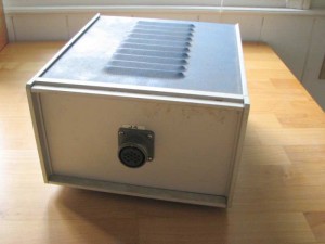
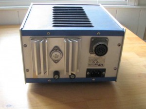
While cleaning, I found a box of old electronics junk that had promising cases. Electronics enclosures are expensive. Salvage can be a good way to keep the cost down. I don’t know what this thing once was, but there are military-style circular connectors on the front and back, two fuse holders, a power inlet, and no visible controls.
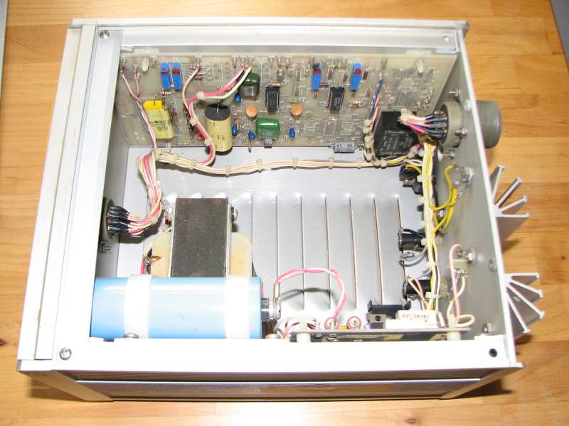
Opening it up, I found this:
There’s a lot of empty space in there! It looks like it was some kind of power supply. Next to the weighty transformer and big blue filter cap, a circuit board carried 7805 and 7806 regulators, several current-sense resistors and an LM324 quad op amp. It also had a power transistor on board and connected to the big TO-3 transistor on the heat sink in the back.
The board on the other side had a couple of high-voltage film capacitors, some ten-turn pots with their positions set with nail polish, two LM324’s and one RCA 4151 voltage-to-frequency/frequency-to-voltage converter. Down in the lower-right corner, it also held a solid-state relay. I’m a little more stumped about what this board was for. Maybe it was more power-supply logic, or maybe some kind of controller.
Tracing out the wiring harness revealed that 120VAC is run to the front connector, with only a fuse between the connector and the power cord. That could get exciting quickly to anyone not expecting it.
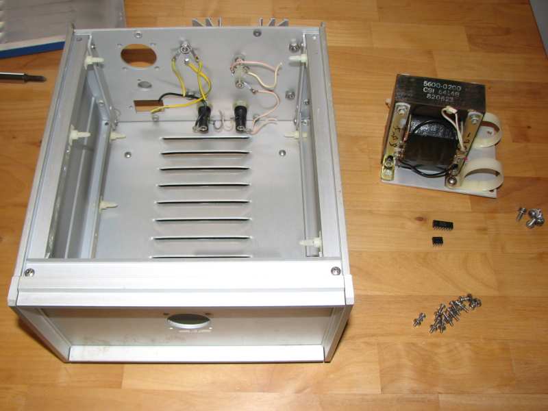
I pulled apart the whole thing, salvaging only the transformer, two ICs, and some fasteners. I tried to salvage all the ICs, but some were corroded into their sockets and could not be extracted without breaking pins. I have not had that happen before.
That’s the final product. I left the fuse holders, the heat sink, and a common ground point in place. They might be useful when this box becomes a transceiver. The front and back panel are 0.125″ aluminum and slide out after a few screws are removed. It will be easy to replace them with new panels for the radio.
The only fixed surfaces in this box on which to mount things are a pair of narrow rails on each of the side extrusions. The bottom is removeable and isn’t set up well to hold circuit boards. I will have to either add a false bottom or come up with a way to mounting the boards at right angles from the sides. Putting the boards flat on the sides, like the original residents of this box, won’t give me enough room, and because the boards are not sized to fit the walls, I would have to improvise some kind of mounting panel or angled standoffs to hold them anyway.
In any event, that problem is solvable. It’s a nice case for what I hope will be a nice radio.


