This post is part of a series on delta-sigma techniques: data converters, modulators, and more. A complete list of posts in the series are in the How Delta-Sigma Works tutorial page.
In the first installment of How Delta-Sigma Works, I presented the basic first-order delta-sigma converter loop. Now it is time to begin digging a little deeper and look at how the loop works. To do this, we will need the mathematical tools of closed-loop control systems. Even without the mathematics, thinking about a delta-sigma modulator as a closed-loop controller can bring insight into how it works.
In engineering, closed-loop control is often used to keep a system working at a setpoint despite environmental disturbances or variations in the system itself. A furnace thermostat is a simple closed-loop controller, turning on the heat when the temperature drops below a setpoint and turning it back off when the temperature is above. Another example is vehicle cruise control. Unlike a thermostat, which usually has a binary output (on/off), cruise control adjusts the engine fuel control to maintain a roughly constant speed. In my car, it does this by physically moving the gas pedal. The environmental variations cruise control can encounter include hills, the quality of the fuel, and headwinds or tailwinds. The closed-loop controller adjusts the gas pedal as needed to maintain constant speed despite these effects.
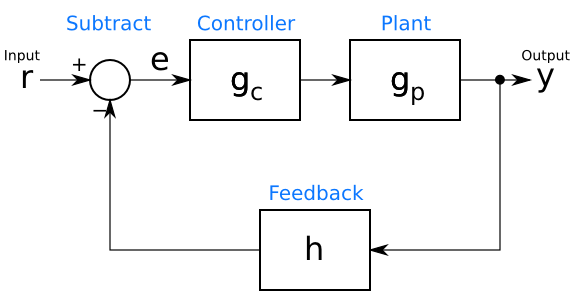
A simple closed-loop control system can be drawn as in the figure below. The reference input, r, is the command input to the controller. In the thermostat example, r is the setpoint temperature, while for cruise control, it is the set speed. The output, y, is the controlled value. This is not necessarily in the same units as the reference input r. For example, in the cruise control, y might be a direct measurement of speed, or it might be something else related, such as a cumulative count of revolutions of the vehicle’s wheels.
In between the input r and the output y is the control loop. At the bottom of the loop, in its feedback path, a block h processes the output y into a form that is subtracted from the input r to create an error signal e. This error signal is an indication of how far the controller is from the desired operating point. The goal of a controller design is to keep e near, if not at, 0. The feedback block h can represent many different things. In the example of a cruise control system with the output y in units of distance, h might calculate speed by computing the derivative of y. In other systems, h might simply scale the value to convert its units. If y and r are already in the same units, such as in a thermostat example, h can pass through y unchanged ().
Now that the error signal has been calculated, it is processed by the controller gc, the output of which goes to the “plant” being controlled. (To a controls engineer, anything being controlled, whether a car, a heating system, or a giant factory, is a plant.) The plant is represented by the box gp. The processing in the controller gc is easy to grasp. The controller calculates some function of its input in order to find the command it should give the plant.
What happens in this plant, gp, may be a little harder to imagine. The function gp is a mathematical model of the physics of the actual plant. It may be calculated from basic principles (a physicist’s delight!), or it may be an empirical model derived from the inputs and outputs of the actual plant. In any event, a reasonable guess at the function gp is necessary before one can design a closed-loop controller.
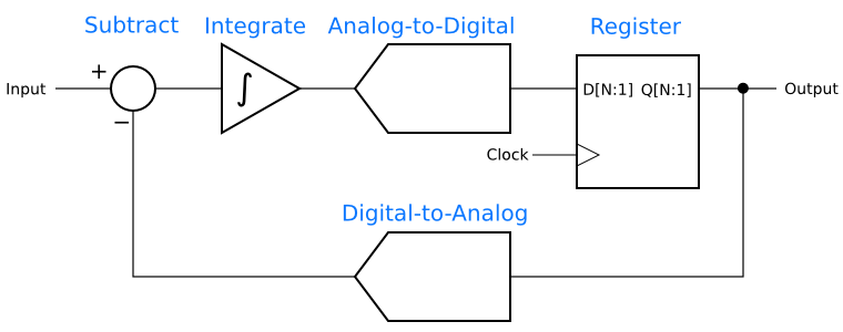
A delta-sigma modulator also has a closed loop, which suggests that perhaps insight can be gained by comparing it to a controller. The first-order delta-sigma analog-to-digital converter from the first installment, is shown again below.
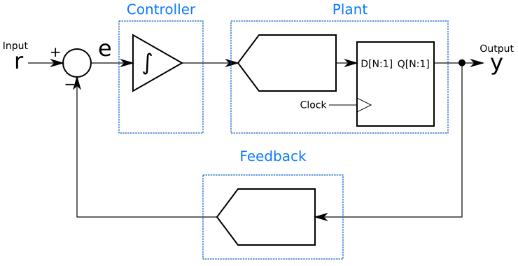
The resemblance to a closed-loop controller is clear when one groups the blocks as in the next figure. The subtractor has the same function in both diagrams, comparing the input to the output. The integrator functions as the controller, gc, and the analog-to-digital convertor and its register are the plant, gp, being controlled. The digital-to-analog converter is the feedback path, h.
This grouping gives immediate insight into how the delta-sigma modulator does its magic: It is a linear controller for an analog-to-digital converter, which is the plant. The controller is always trying to drive that plant’s output as close as possible to the setpoint, and does so by adding up (integrating) the error signal. Also, since the integrator is adding up the history of the error signal, it can be seen that although the output at any given moment may not equal the input, the long-term average will be equal. That integrator will try to keep the long-term average of the error, e, equal to 0.
There are many controllers that can control a given plant. PID (proportional-integral-derivative) controllers are simple and very popular, while more sophisticated controllers can be designed using other techniques. If a delta-sigma modulator is a control loop, it is reasonable to ask if controllers other than an single integrator will result in a better-performing modulator. In fact, other control functions can be used in delta-sigma modulators and can give lower noise or more desirable characteristics in the frequency domain.
Finally, one should not get too carried away with a linear control model. Analog-to-digital and digital-to-analog converters are inherently non-linear, while the mathematics of control theory primarily deals with linear systems. Assuming linear behavior will get us a long way towards understanding delta-sigma techniques, but it is important not to take the analogy too far.
Next in this series: Noise shaping, the frequency-domain secret behind delta-sigma data converters.


