Replacing the BITX 40 BFO

The BITX 40 is all about modifications. The design itself is “cheap and cheerful”, and the circuit board is laid out to invite changes and experiments. I have a list of quirks I intend to fix in mine, and with that the mods began.

First up was a misalignment of the BFO. Each BITX 40 uses a set of 5 matched crystals, four for the IF filter and the fifth for the BFO. The BFO is set up to pull the crystal frequency slightly to put the audio passband in the right place, or at least it is supposed to. On mine, the BFO frequency was just inside the IF passband.

Having the BFO in the wrong place had several consequences. First, receive audio was bassy, running from about 0 Hz to 1800 Hz. This transmits audio frequencies that are not useful for communications and omits the ones around 2 kHz that are especially important. Worse, the passband actually stretch below 0 Hz, into the upper sideband, which meant that my transmitter was not suppressing the carrier. It was sending VSB, vestigial sideband, not SSB. That may be fine if you’re a TV transmitter, but it’s not the kind of clean SSB signal hams expect.

One solution, which Wayne NB6M used on his BITX 40, is to change the “pulling” capacitor in the BFO to put the frequency where it belongs. Instead, I replaced the BFO entirely with a spare channel on the Si5351 frequency synthesizer.

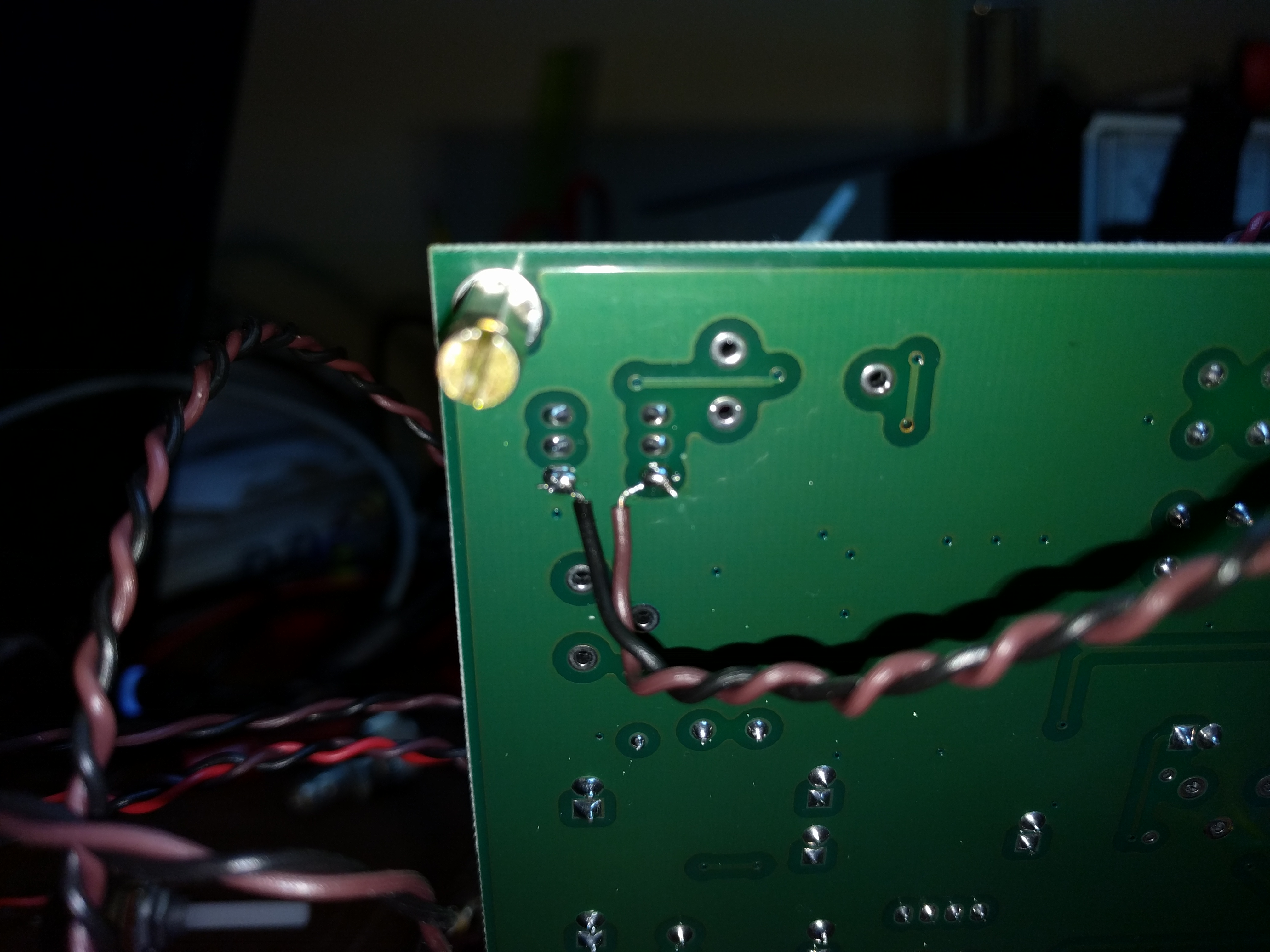
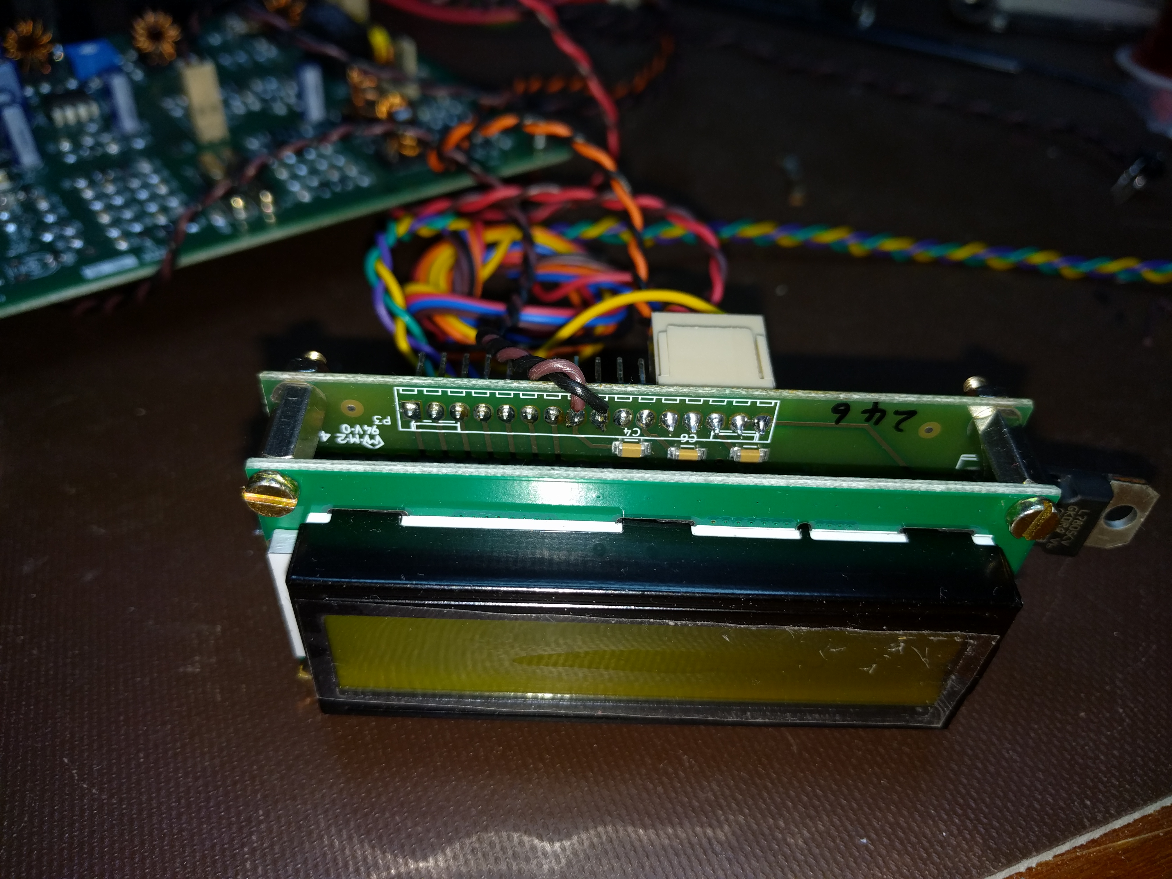
I started off by attaching wires to pins 8 and 9 of the Raduino board. These are Si5351 channel 0 and ground, respectively. For quick progress, I used a twisted pair. When I box it up, I will switch to coax and use a connector to make maintenance easier.

At the other end, I attached the wires to pins 1 and 6 of T4. This supplies the BFO to the second mixer.

Finally, I unsoldered R101 and C106 to remove power from the analog BFO and disconnect it from the second mixer.

With the hardware work done, I turned to the Arduino code. I downloaded Ashhar Farhan’s original bitx40 sketch and added one line of code near the bottom of setup().

si5351.set_freq(bfo_freq * 100ULL, SI5351_CLK0);

Then I turned it on, saw that the BFO was now too far above the IF passband, and with a couple of experiments, came up with the following edit near the top of the sketch:

#define INIT_BFO_FREQ (11997000L)
unsigned long baseTune = 7100000L;
unsigned long bfo_freq = INIT_BFO_FREQ;

With that, I was done. The rig sounds better and works better. I still haven’t transmitted, though. That will take one more mod which I will write about next.

BITX 40!

I’ve decided to build a BITX 40. This petite SSB transceiver sells for a mere $59, some assembly required. As it comes, it puts out approx. 7W, and with some straightforward upgrades it can produce 25W. It comes as a fully-assembled PCB plus most of the parts needed to hook it up. A case, speaker, and a few other incidentals are not included. The board and radio are designed to invite hacking and customization. It is also designed to serve as an introduction to homebrewing for hams who may not be ready to build a radio from scratch. For more information on the BITX-40, see its supplier http://www.hfsigs.com/ and the active and helpful support community at groups.io.

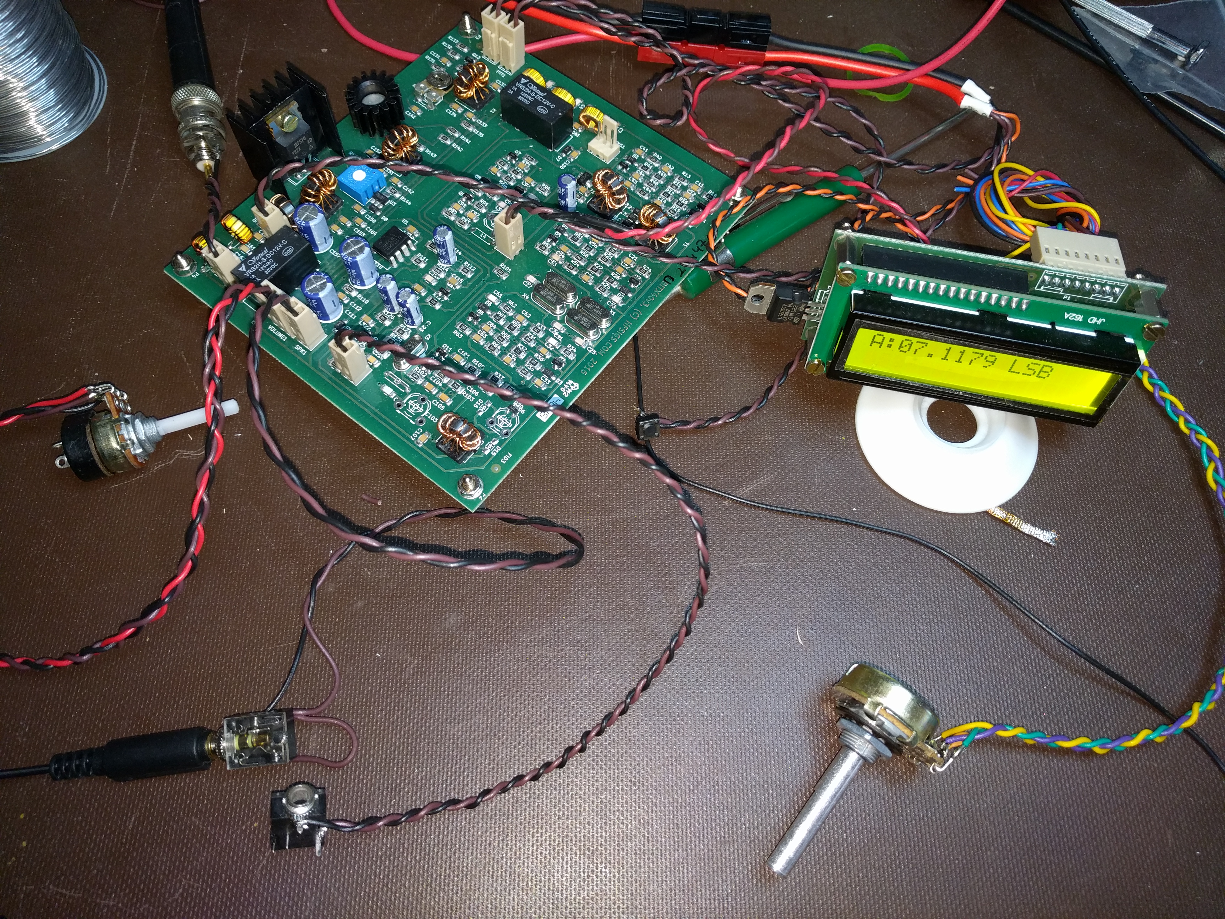
My BITX 40 is operable “al fresco” on my workbench. The included Arduino/Si5351 VFO works fine and tunes the full 40m band. It needs a little bit of work before I can transmit with it. It’s important to understand that the BITX 40 is not a turnkey rig. Many of them ship with small flaws, and figuring out and fixing the flaws is part of the fun. (This is why that helpful community at groups.io is so important.) Mine shares a flaw with Wayne, N6BM’s BITX 40 — the BFO frequency is inside the IF passband, instead of about 300 Hz below the passband like it should. This means that stations I tune sound bassy, I can hear part of the opposite sideband, and when I transmit, the carrier is not suppressed.

(I suppose I could call it “vestigial sideband”, like what NTSC TV uses, but it’s supposed to be SSB…)

Wayne fixed the problem by changing a capacitor in the BFO circuit to pull the frequency where it needed to be. I plan to fix it by disabling the analog BFO and instead use a spare Si5351 output. Having a tunable VFO will let me put the passband exactly where I want. With a little more code, it will also give me passband tuning.

I think I found a bug in the microphone amp that I’m going to take a closer look at, and I found a perfect case at the Mike and Key hamfest in Puyallup last month. I didn’t even try to negotiate the price. It was free!

I’ll have more on my BITX 40 project in upcoming posts.

Going Forth, or maybe not.

Over the years, I keep coming back to the Forth programming language. I admire its lean design and very efficient use of resources, but oh, is it ever quirky. My most recent return was motivated by James Bowman’s J1 Forth CPU, a small but blazingly fast FPGA-based processor.

My ambivalence with Forth started back in the 1980’s, when an engineer named Tom Harsch mentored a very young me in digital electronics and computer architecture. Tom is an all-around engineer, versed in both hardware and software. He had a fondness for Forth, and he introduced it to me. Or perhaps I should say

ME FORTH TOM INTRODUCED

You see, the very first quirk one runs into when encountering Forth is its use of postfix notation to represent operations. While mainstream languages like BASIC and C would have syntax resembling this,

print 2 + 3

Or this,

printf(“%d\n”, 2 + 3);

Forth, in common with German, likes its verbs last. Here’s the Forth version:

2 3 + .

Don’t overlook that period, “.”, at the end. In Forth, that does not end a sentence; it is the command for printing a number.

Postfix notation is intellectually appealing, for several reasons. In postfix, every operation can be expressed with the same basic syntax, so there is no longer a need to distinguish between infix operators (+, -, *, etc.), unary prefix operators (like negation, -), and function calls. They all fit the same basic syntactic framework. Another advantage is that it maps very simply onto a stack-based processor model, which in turn can be implemented reasonably efficiently on many traditional CPUs or which really flies on dedicated hardware.

Forth uses postfix notation to permit the implementation of a simple compiler, which is usually built right into the run-time environment. The simplicity of the compiler results in further bizarre constructs, like the IF…ELSE…THEN statement. Not only are “ELSE” and “THEN” ordered backwards from pretty much every other language in the world, thanks to postfix notation, the “THEN” keyword comes after the code for the ELSE:

( condition ) IF ( then-actions ) ELSE ( else-actions ) THEN

On the bright side, this did give rise to a classic bumper sticker from the Forth Interest Group:

FORTH LOVE IF HONK THEN

Defining a function is straightforward, if you don’t mind punctuation:

: 2times 2 * ;

The colon (:) command defines a new “word” for the language. The next text, “2times”, is the name of the new word. That is followed by the instructions for the word and a semicolon (;) that ends the definition.

So what does this new word do? It multiplies whatever number came before it by 2. “5 2times .” is equivalent to “5 2 * .” and prints the number 10.

This syntax is admirably compact and naturally lends itself to a functional style. On the other hand, what is the name of the word doing after the colon?  In a postfix language, I would expect to quote the name and the function body, then use the defining word. Something like this:

‘2times (2 *) :

Flip that around and add a “lambda” and it starts to look like LISP, but that’s a subject for another time. In Forth, this kind of quirkiness, where everything is postfix except for the parts that aren’t, is standard. It keeps Forth’s compiler simple, but at a cost in elegance.

Syntactic quirkiness aside, Forth has a  few things going for it. First, it makes extremely efficient use of machine resources. A reasonable Forth environment can fit in 4K of RAM and include a compiler, an interpreter, and room for a small application. A full-featured environment is larger, but still takes less resources than equivalent functionality in other languages. Forth is generally fairly speedy, too.

Forth is extremely versatile. The compiler is implemented in an extensible way. You can define Forth words that alter how the compiler works, giving another way to work at higher levels of abstraction.

The philosophy behind Forth encourages programs to be organized in a hierarchy of small, simple functions. Each layer of functions builds a higher level of abstraction than the one that lies below it. I like this kind of well-factored programming, and it would be nice to work in a language that encourages it.

That brings me to the J1 Forth CPU. This compact Verilog core is a work of brilliance, particularly in the way it uses the FPGA’s dual-port RAM in a carefully designed data path to achieve a high instruction rate. The instruction set architecture is pretty much pure Forth, and the implementation was written to be fast. James Bowman’s paper on the J1 (pdf) is well worth a read, and so is the Verilog source code.

Ever since I read the J1 paper, I’ve been itching to find a use for it. (Yes, I know, that’s a solution in search of a problem…) My oft-delayed R2/T2 transceiver project offered a chance. As I thought about what to put on the front panel, my mind strayed to thoughts of touch-panel LCDs. Wouldn’t it be nice to be able to defer most of the user interface decisions to software? It’s much easier to move a button on a screen than to un-drill a hole. eBay has a number of nice touch panels that would fit my chosen case perfectly.

Besides, I’ve been getting in a bit of a rut lately. Though there was a time when I learned every language I could find, lately I’ve been using C almost all the time. How better to shake things up than by implementing a touch-screen user interface in Forth?  My favorite way to learn a new language is to dive into a major project. In fact, I learned C by writing a text editor. Next I learned C++ by writing two text editors. Then I learned Tcl by writing a text editor, and Prolog by writing tax software. (Go figure.)

Eventually I came to my senses. First off, I’m so busy these days that I’m finding it hard to spend any time on the R2/T2, let alone write graphics software for it. A more serious problem, though, is that the Actel FPGA I have handy has only 6K of RAM and limited capability for ROM or flash. To do the graphical user interface, I would want fonts in two sizes, and the J1 on this FPGA would not be able to store even one. I was brainstorming ways to extend the J1’s address space into off-FPGA storage when I had my Arduino epiphany. It does not make sense to spend time engineering complex font storage when a cheap, off-the-shelf processor has 32K of flash and the gcc C compiler at the ready.

Even with the Arduino standing by, I can’t get avoid being busy. No, the R2/T2 will have to make do with switches and knobs. Maybe in the future I can replace them with a touchscreen.

That settled, only one problem remains: I no longer have a problem for the J1 and Forth to solve.

Oh, well…

Updated 1/18/13 to correct the IF…ELSE…THEN syntax.
Rethinking Arduino: A review

I’ll admit it, I was wrong. I’m an engineer by profession, and one for whom designing a microcontroller-based PC board is old hat. I used to look down my nose at Arduino. Its populist appeal and simplified programming language made it a toy in my eyes. I have worked with other boards with similar goals of broad appeal that were poorly designed, with compromises that made the boards unusuable or that overstressed components, making them unreliable. Above all though, “real” engineers design boards for microcontrollers, and they program the microcontrollers using JTAG connections and arcane syntax — or so I thought.

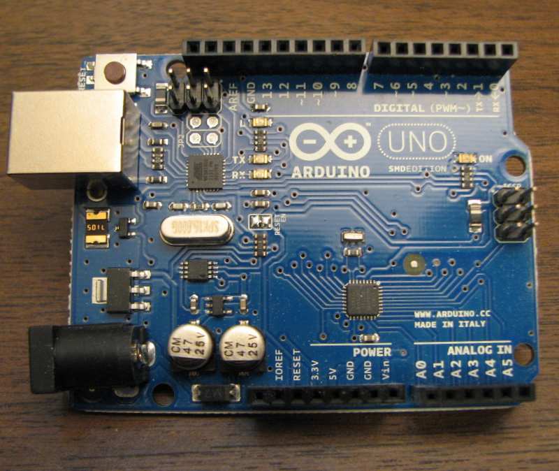
Arduino Uno circuit board

Then a few weeks ago, I was given an Arduino. My perspective has shifted. Arduinos may be populist, they may be the Radio Shack Engineer’s Notebook of the microcontroller world, but they’re also well-designed development boards worthy of any engineer’s attention.

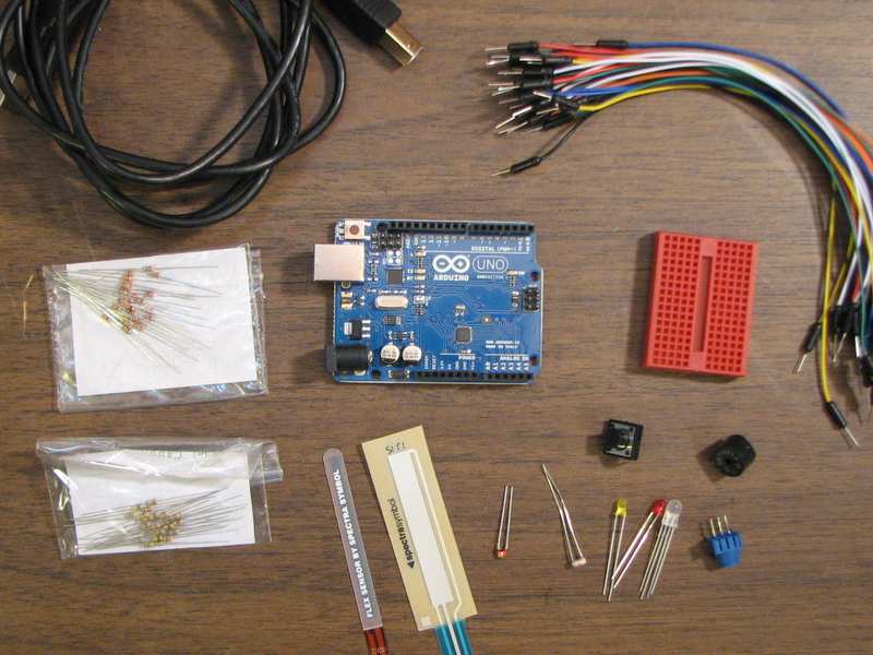
My Arduino came as part of a Sparkfun starter kit, which includes a breadboard, hookup wires, an RGB LED, packs of 1K and 10K resistors, and some fun sensors to play with, including a touch-sensitive resistor and a bend sensor. It amounts to a microcontroller-based building set, and would particularly appeal to anyone who wants to experiment with microcontrollers without having a specific project in mind. Though my son and daughter will be too young for the kit for a few more years, it caught my eye as exactly the sort of thing I might give to one of them to help them learn about what goes on inside a computer.

Sparkfun Starter Kit contents

I set the accessories aside and focused on the Arduino, an Uno model in this kit. Arduino’s current foundation model, the Uno includes a Atmel Atmega328 microcontroller, on-board power supplies (5V and 3.3V), a USB serial interface, a general-purpose LED, and female sockets that break out the microcontroller pins.

The Atmel processor is surprisingly speedy. It has an 8-bit CPU running at 16 MHz, which was plenty of processing power for the things I was trying to do. Perhaps the biggest limitation of the processor is its 2K of RAM. The 32K of flash on-board is great, and conservative programming techniques can fit a surprising amount of functionality into 2K of RAM, but sometimes it’s easier and faster to use a controller with more RAM.

The USB serial interface was a surprise as well. It is implemented by a second, smaller Atmel CPU, programmed to operate as USB-to-serial interface chip akin to the popular FTDI FT232 family. According to Arduino’s creators, the Atmel CPU was less expensive than the FTDI equivalent. Beyond being an interface, the second CPU has a USB bootloader and an ICSP (in-circuit serial programming) header of its own, so it can be reprogrammed just like the Atmega328. The USB CPU is in a tiny QFN package, and most of its I/O lines are not brought out. Still, the ability to reprogram it opens up a lot of interesting possibilities.

Arduino’s native programming environment uses a simplified C-like language. Since I’m comfortable with standard C and prefer test-driven development, I followed Nick Christensen’s detailed instructions on how to set up an Arduino development environment with gcc, Unity, and CMock. The gcc compiler is an industry standard tool these days, and I like Unity and CMock for unit testing.

Then I found out I was a snob. The Arduino wasn’t a toy. As I dug into its schematic and capabilities, I found a well-designed little development board. It was designed with cost-reduction in mind, for sure, but without losing sight of giving access to the entire capabilities of the processor. One processor pin drives an LED, for instance, but that line is also brought out to a header, making it available for other uses. The analog input pins are brought out without analog buffering, so they are available for digital I/O. Even the serial interface pins used to download code over USB can be repurposed.

There are other low-cost development boards, some directly competing with Arduino and others aiming for a slightly different audience. Here Arduino’s advantage is its popularity. Between Radio Shack and Micro Center, I can buy an original or cloned Arduino at retail from at least four stores within three miles of my house. That is surely not true for the entire world, but Arduino and software-compatible clones are also readily available online.

For my last small project, when I needed a microcontroller, I picked an inexpensive MSP430F2011 because TI’s EZ430 USB stick (which was a freebie from TI) could serve as the programmer. Next time, there’s a good chance I will use a genuine Arduino, one of the clones, or maybe just use these development tools with a plain Atmega328.

Yep, Arduino is worth a look, even for those used to the traditional “professional” world of microcontroller design.