PCB routing techniques for ADCs

PCB layout is fun, especially when you are trying to eke the best performance out of a component.  Last week, I finished the PCB layout for the AK5388 analog-to-digital converter (ADC) I chose for my digital ham radio transceiver project. Let’s take a closer look at some of the design details…

My top priority was to keep digital lines away from sensitive analog signals. The quickly-switching edges of digital signals carry lots of high-frequency components, which readily couple into any neighboring line. It’s best to keep this high-frequency crud away from quiet analog signals. It’s not great to let it couple instead into other digital lines, but digital inputs are pretty tolerant to it and rarely have problems.
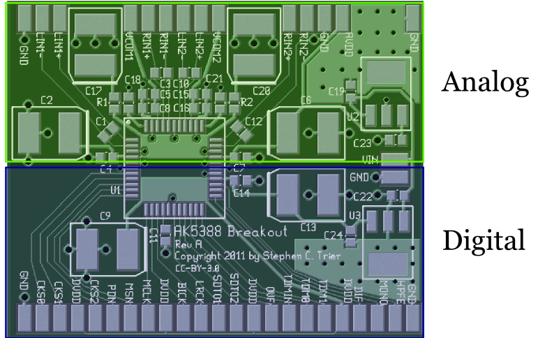
AK5388 board with an overlay showing how the analog and digital sections are separate.

The AK5388 pinout helps a lot with this separation requirement. As is done in many ADCs, all of the digital pins are on one side of the chip, and all of the analog pins on the other. When laying out a mixed-signal board (that is, one that has  both analog and digital elements), I like to draw a line across the board before I even start to place the parts, with all analog components going on one side and all digital on the other. As the placement and routing progress, that line will move and may even change into a zig-zag, but the idea remains: Keep the analog stuff on one side and the digital on the other.

On the AK5388 breakout board, the analog-digital border remains a straight line. Everything in the top half of the board is analog, and everything in the bottom half is digital.

Another reason to have a clean split is the return currents and their IR drop. Remember that current flows in a loop. When any of those digital lines changes state, it charges a small capacitance at the other end, and the current used to do that charging flows back through the ground plane. At high frequencies, that return current is largely confined beneath the digital line that caused it. On top of that, the return current causes a voltage gradient underneath it, thanks to Ohm’s law and the resistance of ground. (V = IR)  This voltage gradient can act as an additive noise source on analog signals that are routed near it. The careful split in this board’s design will help keep the digital return currents from affecting the analog signals.

Another feature of the board is that it has local analog and digital power supplies for the ADC. The power supplies are located in their own area, again to try to limit noise caused by the return currents. In the picture below, the power supplies are highlighted in yellow.
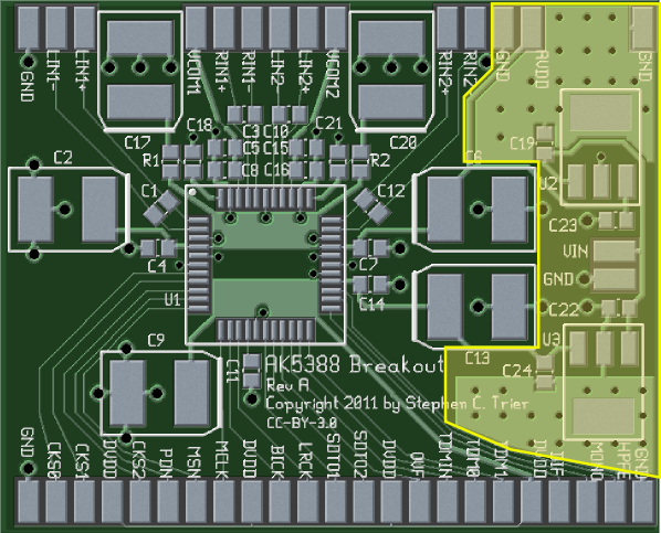
The AK5388 breakout board with the power supply location highlighted.

The voltage regulators used here (uA78M33CDCY and uA78M05CDCY) are in SOT-233 packages, which have a large lead on one side to help with heatsinking.  The board is laid out with some extra copper area to act as a heat spreader for each SOT-223, along with a bunch of vias tying the top-side copper to the ground plane. These vias have a thermal role, not primarily an electrical one, as they help transfer heat from the top-side heat spreader down to the ground plane to further spread it out.

Although there are ways to estimate the thermal performance of a heat-spreader design like this, I didn’t do them. Frankly, I don’t have any idea whether this board’s thermal provisions are adequate. Even at the bargain price of $5/square inch to have this PCB fabbed, adding copper just for thermal management gets expensive. If the heat-spreading area turns out to be insufficient, I’ll find a way to attach a heatsink to the top side of the regulators, solder a piece of brass to their large lead, or something along those lines to remove the heat more efficiently.

Finally, take a look at the decoupling capacitors. C4, C7, C11, and C14 are 100 nF capacitors, each on one power-supply input to the ADC. They are positioned as close to the ADC as I could manage. One could argue that their positioning is not quite perfect because there is a relatively long path from their grounded side to the closest ADC ground pin. It goes through two vias and the ground plane. I have never looked into whether this makes a significant difference. If you know, leave a note in the comments and tell me!

In any case, the 100 nF capacitors are multi-layer ceramic capacitors (MLCC), which have a low equivalent series resistance (ESR) and inductance (ESL). Those characteristics make them ideal for decoupling high-frequency noise on the power supply lines.

Next, C2, C9, C22, and C23 are big 10 μF decoupling capacitors. These are positioned a little farther away. They are aluminum electrolytic capacitors, which have a higher ESR and ESL than ceramic caps. (10 μF ceramic capacitors are expensive!) These capacitors are better for removing low frequencies, including the audio range, from the power supplies. For that reason, I did not see much harm in putting them a little farther from the ADC, with the extra inductance and resistance that implies. Besides, these things are BIG! If they were any closer to the ADC, routing the signal lines in and out would get pretty challenging.

One trick for getting the decoupling capacitors closer is to put them on the back side of the board. The distance through a via would be much shorter than the distance needed here. I wanted a single-sided design here, so that wasn’t an option, but it’s something to keep in mind.

I won’t claim that I know everything about designing for a high-performance ADC. In fact, it’s possible that someone more experienced is planting their face in their palm right now, saying, “I can’t believe he did that!”  (If that’s you, by the way, drop me a note to let me know what the problem is, would you?)  That said, what I did here is based on app notes and other materials from a number of semiconductor companies, including Analog Devices and National Semiconductor, and I think it’s pretty sound.

I ordered the parts for this board today. It doesn’t take long for UPS to get things to Ohio from Digi-Key’s home in northernmost Minnesota, but it’s always a long wait when I’m itching to try something out.

I’ll catch you next week with more on electronics, DSP, and ham radio.
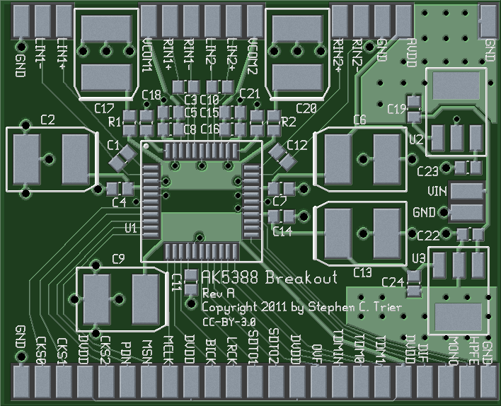
PCB layout for the AK5388 ADC breakout board

I had some time to myself this weekend and was able to get the AK5388 breakout board routed. The board carries an AKM AK5388 audio DAC, which has 24-bit output and up to a 123 dB signal-to-noise ratio. My plan is to build up this board, evaluate it to verify that it works as I expect, then use it as the ADC stage in a DSP-based ham radio receiver.

Moving the schematic from gschem to PCB was really easy. This was my first time using PCB’s “Import schematics” command. It was a breeze, especially compared to the old way of doing it, the gsch2pcb command. That command worked well enough, but I could never get it done without checking the documentation or a howto online. “Import Schematics” required no such thing. Bravo to the PCB developers!

As with the FPGA board, I laid out the board with a solid groundplane on the back and all components and traces on the front. That way, it can be placed on a piece of copperclad board, for skywired construction, without risk of shorts to ground. It’s also good for noise performance.

Photorealistic view of AK5388 breakout board, top side

The square chip in the middle (QFP, U1) is the AK5388. On the right edge are a 7833 and a 7805 voltage regulator, for the digital and analog power supplies, respectively. The board includes some heatsink area around the regulators (U2 and U3), with thermal vias to stitch the heatsink to the groundplane on the back. The rest of the components are decoupling capacitors, lots of decoupling capacitors, plus two resistors that also help control noise. A 24-bit ADC needs quiet power supplies!

As you might expect, the bottom side is kind of boring:

Photorealistic image of the bottom side of the AK5388 breakout board

That’s the ADC board so far. Although I have Gerber files now and could go order the boards, I’m going to order the parts first this time and test-fit them on a printout of the layout.

gedasymbols.org is a great part of using gEDA

I’ve joined up as a contributor to  gedasymbols.org. This great resource, run by DJ Delorie, hosts schematic symbols for gschem and footprints for gEDA’s layout software, PCB. A search engine helps locate symbols and footprints, and gedasymbols includes links to other libraries off-site, such as Dan Luciani’s extensive footprint library. Gedasymbols.org has been hugely useful every time I do a design in gschem or PCB, and I’m happy to have something I can contribute back.

Gedasymbols has the symbols and footprints for the A3PN250 FPGA and AK5388 audio ADC breakout boards, plus symbols from an MSP430 project that I haven’t posted here yet.

As for other hacking recently, I’ve done parts placement for the AK5388 board but haven’t started routing it. I also need to make a better feedthrough panel for my antenna. I’ll have more to say about those two projects in a future post.

Comments welcome!

AK5388 audio ADC breakout board design

A few weeks ago, I picked the AKM Semiconductor AK5388 as the analog-to-digital converter for my receiver design. This high-performance audio DAC has a 24-bit output with up to 123 dB signal-to-noise ratio (A-weighted).  I hope that the narrower bandwidths of a communications receiver will beat that. The idea is to do the automatic gain control (AGC) in digital, so that the receiver will not need an analog AGC loop. I hope that a preamp or attenuator at the front end will be enough to make up for the limited dynamic range of the AGC.

Now, I am aware that getting performance like that requires great care in the details of the design and layout, but if this wasn’t a challenge, it wouldn’t be nearly as much fun!  The AK5388 datasheet does give me some concern, because it does not make much mention of the techniques needed for a high-performance DAC. Admittedly, datasheets from Japanese manufacturers are often thinner on details than those from the leading US suppliers, and this one is much more complete than some. On the other hand, it may be that the datasheet is glossing over any coddling this chip will need.

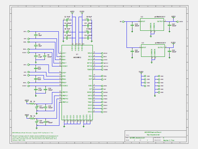
There is one way to find out, and that is to start breadboarding. This is a surface-mount part, so I have designed a breakout board very much like the board I built for the Actel Microsemi A3PN250 FPGA. The schematic is below.

AK5388 ADC Breakout Board schematic

The schematic largely follows the “System Design” section of the datasheet and the example of the AKD5388-A evaluation kit (PDF). It’s not strictly a breakout because I included on-board analog and digital power supplies. An ADC like this needs quiet, local power, so I picked some reasonably quiet supplies and put them on-board. I chose 7800-family regulators from TI because they have reasonable noise specifications. I almost went with other choices that were explicitly designed for low noise, but they were quite a bit more expensive for not much less noise. The AKD5388-A kit uses an uA78M05 and claims to be able to obtain the full dynamic range of this ADC, so there is little reason to spend more at this point.

I’m using the analog power supply as the voltage reference. I considered a dedicated reference, which would be more expensive but perhaps lower noise. Here, too, I followed the lead of the evaluation kit.

The PCB layout should be straightforward. I like to build by skywiring components over a groundplane, so this breakout board will be designed to sit directly on a groundplane, with all components and connections on the top side. All external wiring points will be pads on the PCB, ready for soldering, just as with the A3PN250 FPGA board.

I’m excited about trying out this part. What do you think? Comments welcome!

It’s antenna time!

For years, I’ve been a ham without an antenna. My excuse, while I worked in academia, was that I could use the university club station any time, but in truth, I’ve always been the kind of ham who goes through more soldering iron tips than QSL cards. That said, since I’m building a radio, I need an antenna!

As I’m sure you know, a bewildering variety of antenna designs are available. I lusted after a GAP vertical for a while, then over an S9. On a small city lot with inconveniently-placed power lines, there wasn’t much else that would fit. Eventually, though, and with some encouragement from my dear wife who didn’t see the appeal of spending hundreds of dollars on an antenna, I chose a wire vertical. The whole thing, except for the window bulkhead and the rope, came from junkbox parts.

The wire is suspended from the side of the house by a rope poking through a gable vent. The antenna is about 7.5 meters long because that’s how high the vent it, but that should be a decent compromise length for 40, 30, and 20 meters.  The wire lands right at the property line, a few feet from a convenient basement window. I replaced the screen in the window with some polystyrene sheet, in which I cut a hole for a BNC bulkhead feedthrough.

I added a few radials to the bottom of the antenna, and I was in business. (I did learn, as have thousands of hams before me, that cheap soldering irons don’t work well in windy, cold weather.)

Then it was time to hook up a radio. I went for my 40m Sudden receiver first. It’s a simple direct conversion rig with an NE602 as oscillator and mixer and an LM386 as audio amplifier. I plugged it in and quickly found an AM broadcast station, which turned out to be Radio Croatia. That got me an idea of which way to tune to find the ham band. The first station I heard was N6KI, who was running a frequency for the California QSO party.

I was hoping to get down to 7.038 MHz and tune in some PSK31, but for some reason the Sudden didn’t want to tune below the phone band. That’s odd, because when I first plugged it in, I heard a wall of “CQ SS CQ SS” crashing in on multiple frequencies. Yes, I happened to build the on Sweepstakes weekend! I had plenty of stations to listen to.

I got out my NorCal 40A, but alas, the power cord somehow was packed separately from the rig and I had no easy way to power it up. It was the same story for my 30m rig. Maybe this is a sign that I should convert to Anderson Powerpoles.

Anyway, it’s not a great antenna, but it will be enough to get started and make some QSOs. Best of all, it’s mine!

Now, if only I could remember what box I packed that power cord in…

Comments always welcome!

(Credit to Dan Tayloe N7VE for coining the line about soldering iron tips and QSL cards.)