I’m continuing to work on my R2/T2 transceiver project as time allows. My goal is to get on the air before the sunspot cycle peak passes. That gives me a little time yet, but at the rate I get things built around here, it’s going to be a close race.
Even when building a radio from kits, as I am here, there are many decisions to be made. When I bought the KK7B R2 and T2 kits, I had no thoughts about what to use for a local oscillator. Technology has advanced mightily since then, and now I have the option of an Si570 frequency synthesizer. This little chip provides a precise, low-noise digital clock at programmable frequencies between 3.5 MHz and 1.4 GHz, depending on the variant one buys.

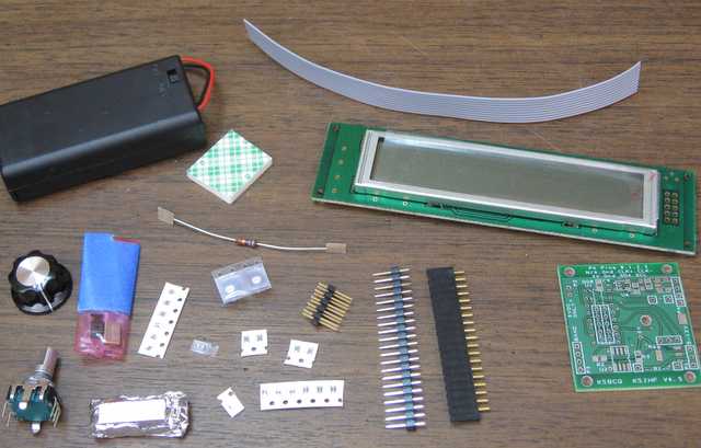
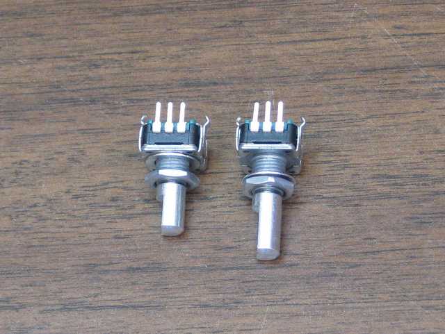
After looking around a bit, I picked John Fisher K5JHF and Kees Talen K5BCQ’s SI570 controller/frequency generator kit. Once it arrived, I had trouble figuring out how to fit it into my case. This case has a 0.125″ thick aluminum front panel. The threaded bushing on the kit’s encoder/switch was not long enough for this thick panel and a mounting nut, let alone a washer. There were also some mechanical things I didn’t like about the circuit board. I thought a bit about designing a new board for the parts from the kit, but I decided I could fix the worst of the problems with a new encoder. A little browsing at Mouser turned up an extremely similar model that had the longer bushing I needed. It even has the same footprint.

I’m a little stumped by how similar they are. The Mouser one (on the right) is from Bourns, but looking over the data sheet, I couldn’t find a model with a bushing and shaft length matching the one from the kit. The body of both units is essentially identical. Hopefully they are electrically close enough, too. I had to guess at how many pulses per rotation it should have.
I’m still chewing on another mechanical question. The kit is designed to have the PCB soldered to one end of the LCD, with the encoder mounted off the PCB, on the right of the LCD. I want to have the tuning knob centered below the LCD, so the PCB is going to have to stay with either the LCB or the encoder, and the other will have to be connected with wires. My initial thought was to mount the encoder on the PCB and wire the LCD remotely, but I’m beginning to favor mounting the PCB on the LCD and running wires to the encoder. The connection between the PCB and LCD will involve high-frequency digital signals, while the connection to the encoder is analog switch closures that have less potential for RF interference. It would be better to have the LCD signals cover a shorter distance so they radiate less.
On top of that, putting the PCB and the LCD together will make it easier to surround them with a shield.
All this rambling aside, yes, I’m making slow progress on the R2/T2 rig. When I’m working on a project, sometimes I spend a lot of time doing and other times I spend my time thinking. I’m a little out of my element with the mechanical design of the radio, so lately I’ve been planning the design carefully.