I’ve made lots of small steps on the A3PN250 FPGA breakout board the last two weeks.
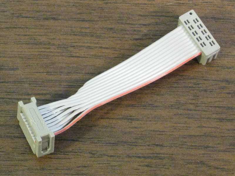
Firstly, I built an JTAG adapter cable to work around a wiring error on the PCB. When I laid out the board, I accidentally numbered the pins on the JTAG connector DIP-style instead of ribbon cable style. That meant that all the pins except for pin 1 were wired wrong. After thinking a bit about the options, which included scrapping the board and starting over, or skywiring in corrected wiring for the connector, I decided the cleanest solution was to make a custom JTAG cable that moved the pins around where they belong. I’d seen other cables built this way. I asked myself, “How hard could it be?”
An order went to Mouser for a 6 inch, 10-pin ribbon cable with header sockets on both ends, plus two more 10-pin sockets. My thought was to cut one end off the assembled cable, rearrange the wires, and put a new socket on. I bought two so I’d have two chances to get it right. Once the cable arrived, I realized it would be better to cut it in half, so I had the option of making another cable like this down the road should there be another way to wire JTAG wrong! I made a few snips with my wire cutters, separated the wires of the cable, and started putting them in the right order. The cable was numbered 1, 2, 3, … 9, 10, but now I needed 1, 10, 2, 9, 3, 8, 4, 7, 5, 6.
It really was easier than I expected. Getting the ten individual strands to lie flat and in the right order inside the new socket was a bit of a chore, but not too hard. I squeezed the socket closed and checked it for the right wiring pattern and no shorts, and to my surprise, it came out fine.

In hindsight, another fine solution would be to use single-pin jumpers like these from SparkFun. I chose to build a cable so I wouldn’t have to fiddle with ten jumpers every time I wanted to connect the programmer.
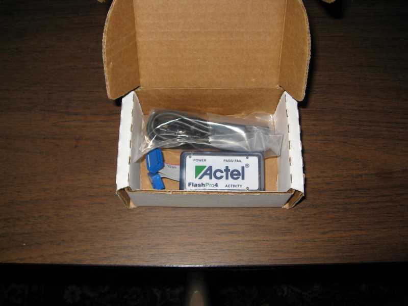
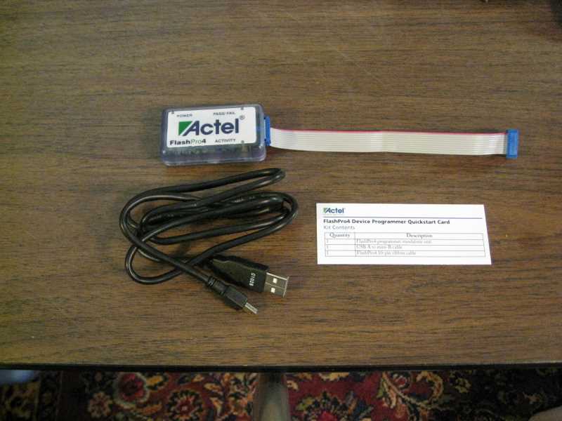
With the cable built, I could unpack the programmer. My original plan was to use a borrowed FlashPro 3 programmer, but the next-generation FlashPro 4 was so cheap ($50 from Mouser) that I bought my own. I was a bit surprised by the minimal packaging. It arrived in a plain white, small cardboard box. Inside was a standard USB cable (type-A to mini-B), the FlashPro4 pod, the 10-pin JTAG cable, and a slip of paper. There was no DVD of software, no fancy box graphics, and no plastic wrap. If that is why it’s $50 versus the $100+ that the now-obsolete FlashPro3 cost, I’m all for it.


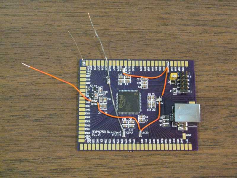
With a cable built and a programmer at hand, I was almost ready for the smoke test. In other words, I was going to apply power for the first time. I wired up the board for power. All four I/O banks plus the JTAG interface are wired together with the orange wires, and the core and PLL are wired with the grey wires. I tacked on a ground wire, too.

With my power supplies set at 3.3V (for I/O and JTAG) and 1.5V (for the core and PLL), I was ready to go. I reached for my banana-plug cables… and they weren’t there.
Now, I should explain that I thought I unpacked all the electronics after our last move, but this is my first significant project since then. It seems that the cables I need are still in a box somewhere… somewhere in the basement.
Hence, no smoke test this week, but more time cleaning the basement.