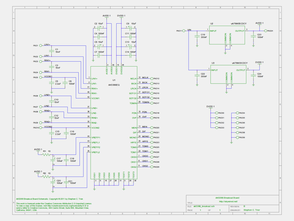
For the last month or two, a breakout board for the AKM Semiconductor AK5388 analog-to-digital converter has been my main project. Here’s an update on where it stands.
When I last posted about the board, I was waiting for parts to arrive so I could check their fit on a printout of the PCB. After the capacitor footprint error on the FPGA breakout board, I was feeling a bit cautious. The parts arrived and fit fine! I checked out the ADC on its QFP footprint, and it was perfect. Then I tried the big capacitors on their EIA 3216 footprints, and those were fine, too.
Fixing the schematic
I ran into some problems with the schematic when I did the PCB layout. One problem was that multiple pads named “GND” or “DVDD” were consolidated into one. A second problem was that the names I had assigned the pads were not visible in PCB, meaning I was in for a slow process of finding each one on the schematic in order to add the right label to the PCB’s silkscreen. I found a great solution, though.
The fix to both problems was to name the nets, not the pads. I restored all the pads to their boring PAD1, PAD2, … reference designators and named the schematic nets after the signals. Now, when I hovered the cursor over one of the pads in PCB, a little tooltip popped up and told me the net name connected to the pad, among other things. Labelling all of the pads took only a few minutes. I wish I had known about this trick when I did the A3PN250 FPGA board!
Secondly, using conventional reference designators to name the pads solved the problem with the DVDD and GND pads.
These changes resulted in the rev B schematic. A PNG version is above, and I’ll post the editable gschem version on the AK5388 breakout project page.
I have ordered the boards, and I will have more to say about that next week.
What do you think? Comments welcome!

 I’ve joined up as a