Digging up a Dinosaur – a Boatanchor at the Children’s Museum

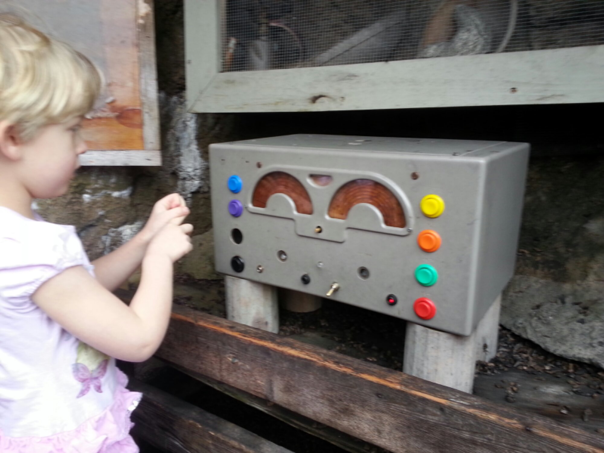
Last weekend, I took my children to the Imagine Children’s Museum in Everett, WA. On the roof, my daughter found this National NC-173 as part of a “dinosaur dig” exhibit. It may have been gutted. At the very least, the controls are certainly not original! The colorful, kid-resistant buttons cause a speaker to play a variety of recorded messages, supposedly radio communications with a base camp.

It has been painted so many times, I could hardly identify it. Through the paint, I found an engraved “80”, “40”, and “10-20” by what may have been a band switch. Peering harder, I could just make out the model number.

I’m not a boatanchor guy, and some might bemoan the loss of a historic radio. It made me smile to find it, though, and my daughter enjoyed playing with it. That’s enough for me.

image


When I brought my children to the Imagine Children’s Museum (Everett, WA) last weekend, they showed me the “dinosaur dig” exhibit on the roof. There we found this National NC-173 receiver, of Kon-Tiki fame. It looks like it has been gutted. The controls certainly aren’t original. The brightly-colored, kid-resistant buttons cause it to play recorded messages from a “base camp” to the pretend-paleontologists at the dig.

I had to peer through layers of paint to read the engravings and identify it. The best remaining marking is “80”, “40”, and “10-20” by what may have been a band switch. I could barely find the model number under all the paint.

I’m not a boatanchor guy, and I understand that some might bemoan the loss of a classic receiver. My daughter enjoyed playing with it, though, and it made me smile to find it, so it’s all right with me.

KK7B R2 receiver: lifted pads, a scorched board, and it works anyway

I’m slowly making progress on my KK7B R2/T2 transceiver project. At my last report, I was waiting for replacement capacitors to arrive. They did, and I pulled out my ancient solder-removal iron, a Radio Shack unit from who knows how long ago.

Either my unsoldering skills are rusty or I was too impatient, or both. I managed to lift four pads, completely demolishing one. The other three were salvageable. I’d like the board to be perfect, but having it work is an acceptable substitute.

The new caps went in easily, with only a little fiddling to wire around the ruined pad. Better yet, the excessive bias current I saw before the replacement is gone! The board is supposed to be adjusted to 100 mA current. It used to start at 120 mA, with the bias adjustment set to its minimum, and drift its way up to more and more current from there (going as high as 200 mA before I’ve lost my nerve and switched it off). Now it starts at 84 mA and… drifts its way up from there to 130 mA and more.

OK, so one problem was solved. I can always increase current with the bias adjustment potentiometer.

After scratching my head a bit, I finally noticed one small sentence in KK7B’s articles on the R1 and R2. The audio output transistors need a heat sink, do they? Oops! I dug around a bit in my junk box but couldn’t find anything that would fit. The articles say the audio amp will drive a pair of headphones fine without the output transistors, so I decided to take them out.

I recently got a Sparkfun hot-air soldering station (a Sparkfun Free Day prize!) and thought I’d give it a shot. Sure, hot air is usually for surface-mount parts, but solder is solder, right?  Not being sure how to set the airflow and temperature settings, I set both on the high side, put some flux on the output transistors’ pads, and went for it. The result wasn’t pretty:
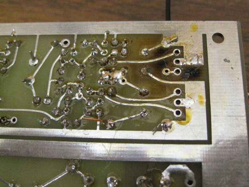
Oops... A scorched R2 PCB

Yes, I scorched the board. Oops. Between this and the lifted pads, I think I need to work on my unsoldering skills.

Since the transistors are 50 cent parts (TIP29/TIP30), I unsoldered them the easy way: I cut the leads, removed the leads from the board with my conventional iron, then cleaned out the holes with my solder sucker. I didn’t damage any pads this time!  (The picture above was taken after all of these steps.)

A little more soldering to hook up a BNC and some other goodies, and the board was alive!
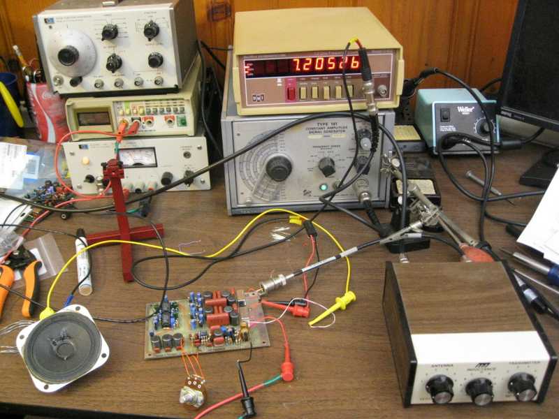
R2 on the bench, surrounded by test equipment

That’s a Tek 191 signal generator as the VFO (variable frequency oscillator), with a frequency counter as the readout. That’s an MFJ QRP antenna tuner in the foreground.

I didn’t build a phasing network yet, so I drove only one VFO input. That causes the R2 to function like a conventional direct-conversion receiver,receiving both sidebands simultaneously. That said, it works. I was able to hear signals, though frankly many were quite hard to copy. I’m not sure what else might be wrong.

The frequency counter spits out a lot of digital noise. I learned to flip it on only to spot-check my frequency. It’s a lot quieter in standby mode.

Did I mention that IT WORKS?

Despite the success, I’ve been struck by a bit of paralysis in moving forward. There are so many choices to make for integrating the radio.

  • What kind of VFO should I use? Should I design my own or buy a kit?
  • Which modes should I include?
  • How much power output do I want?
  • What power amp should I use? Should I design my own or buy a kit?
  • Which case should all of this go in?
  • What microphone, and microphone connector, should I plan for?

Keep in mind that this is supposed to me my fast route to getting on the air, so I’m thinking kits for both the VFO and amp. Besides, with as busy as it has been at work lately, it is nice to sit back and just build something.

It’s not a pretty project any more, but it works! Hooray!
R2 receiver update: Time for new electrolytic capacitors

Crunch time at work has been limiting my basement tinkering, but I recently found time to work on my R2 receiver a bit more. It is pulling excessive bias current, which had me scratching my head. The audio power amplifier bias is supposed to be adjusted so that the whole board pulls 100 mA, but it’s taking 120 mA even with the bias pot set to its minimum. After double-checking all of the component values and verifying all of the bias voltages on the board, I was left scratching my head. Then I remembered the age of the kit. Even while building it, I had doubts about the electrolytic capacitors…

This R2 kit includes 15 Panasonic Z-series electrolytic capacitors. Aluminum electrolytic caps are good at one thing: Lots of capacitance at a low cost. In nearly every regard, they have inferior performance, with high equivalent series resistance (ESR), inductance (ESL), and, yes, a short lifetime. I’m not sure exactly how to translate the lifetime specifications for electrolytics to room temperature storage, but the rule of thumb tends to be that they can tolerate 5 years on the shelf, after which they require a “reforming” procedure. Reforming them at that point can get them to last another 5 years or so. After that, figure that they are shot. Old electrolytic capacitors can have excessive leakage current. In extreme cases, this current is enough to heat them up excessively and they go bang! The capacitors on this board are old enough to vote. Maybe one or more of them are to blame for the extra milliamps.

I had a little trouble finding the perfect capacitors, but then I was looking for performance at least as good as the original. This was perhaps foolish, because I couldn’t find data on the Z-series caps. Panasonic discontinued them in 2000. In lieu of further information, I arbitrarily went for high-quality models from a favorite manufacturer. In some cases, these were nearly double the price of the cheapest options, a breathtaking 23 cents versus 12 cents, quantity one. Seriously, replacements for all of the caps cost all of $2.85, including a few spares for good measure.

My one mistake so far is to forget about the T2 transmitter. If the R2’s capacitors are bad, the T2’s surely are as well. Maybe the spares I bought will end up there.

Troubleshooting is half the fun of this stuff. Who needs sudoku when you can puzzle out a misbehaving circuit?

Building a KK7B R2 phasing receiver

Hi, I’m back! It was a rough week, with a death in the family. As it ended, I found some time for some “solder therapy”. There is something good for the soul in putting together electronics. I don’t know if it’s the scent of the rosin or the satisfaction of seeing a project come together. All I know is it’s good for me.

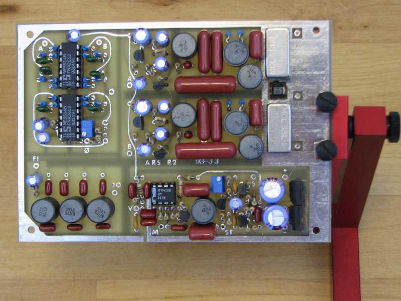
KK7B R2 receiver, top side

The target of my soldering was my KK7B R2 receiver kit. This is the companion to the T2 I wrote about a few weeks ago. To my surprise, the R2 was easier to put together despite the higher part count. The components are larger, forcing a less dense pin matrix, and the board is separated into sections: mixers and diplexers, audio phase shift, low-pass filter, and audio amplifier. Conveniently, the board uses jumper wires (not yet installed on mine) to connect the sections. The intent appears to have been to make it easier to extend the board by swapping in a different phase shift network or adding alternate filters for CW or contesting, but it will make the board easier to debug as well, since I can bring it up a section at a time.

Keep in mind that this is a vintage kit that is no longer available, but updated versions of the design are still produced by Kanga US.

The board surprised me with its heft. I work mostly with surface-mount digital boards where the fiberglass PCB is the heaviest component. This board, though, weighs 134 g (4.7 oz), which is a lot for 100 cm2 (16 in2). The shielded inductors are the culprits. Each black cylinder in the photo is the ferrite shield of an inductor. Each inductor is noticeably heavy for its size, and this board has 10 of them.

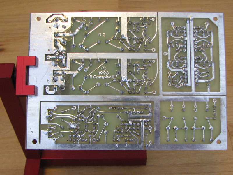
KK7B R2 receiver board, bottom side

Once I wash the flux off (it’s not as much fun as soldering), the next piece of the puzzle is to build or buy a VFO. Rick, KK7B, designed a companion VFO for these boards, but it is out of production at the moment. I’m thinking about one of the Si570 VFOs out there. This little chip offers a very low phase noise synthesizer with tuning in steps of a fraction of a Hertz. Having this on a single chip was a pipe dream when the R2 and T2 were designed.

After that, I’ll need to build a power amplifier to boost the T2’s milliwatts up to a reasonable level — at least a watt, maybe as much as 50 W. Finally, I will have to integrate all the pieces into a working rig. Professionally, I do a lot of microcontroller work, so it’s tempting to build a fancy digital control panel with circuitry to integrate every R2 and T2 option imaginable. Instead, I’m trying to keep myself to something simple: one band, SSB only, and a digital frequency readout as the only frill.

I still have to pick the initial band. I’m torn between 20m, my favorite for PSK31, and 40m, which I like for SSB. I’m after whatever DX I can land in either mode. What band would you recommend?

It’s antenna time!

For years, I’ve been a ham without an antenna. My excuse, while I worked in academia, was that I could use the university club station any time, but in truth, I’ve always been the kind of ham who goes through more soldering iron tips than QSL cards. That said, since I’m building a radio, I need an antenna!

As I’m sure you know, a bewildering variety of antenna designs are available. I lusted after a GAP vertical for a while, then over an S9. On a small city lot with inconveniently-placed power lines, there wasn’t much else that would fit. Eventually, though, and with some encouragement from my dear wife who didn’t see the appeal of spending hundreds of dollars on an antenna, I chose a wire vertical. The whole thing, except for the window bulkhead and the rope, came from junkbox parts.

The wire is suspended from the side of the house by a rope poking through a gable vent. The antenna is about 7.5 meters long because that’s how high the vent it, but that should be a decent compromise length for 40, 30, and 20 meters.  The wire lands right at the property line, a few feet from a convenient basement window. I replaced the screen in the window with some polystyrene sheet, in which I cut a hole for a BNC bulkhead feedthrough.

I added a few radials to the bottom of the antenna, and I was in business. (I did learn, as have thousands of hams before me, that cheap soldering irons don’t work well in windy, cold weather.)

Then it was time to hook up a radio. I went for my 40m Sudden receiver first. It’s a simple direct conversion rig with an NE602 as oscillator and mixer and an LM386 as audio amplifier. I plugged it in and quickly found an AM broadcast station, which turned out to be Radio Croatia. That got me an idea of which way to tune to find the ham band. The first station I heard was N6KI, who was running a frequency for the California QSO party.

I was hoping to get down to 7.038 MHz and tune in some PSK31, but for some reason the Sudden didn’t want to tune below the phone band. That’s odd, because when I first plugged it in, I heard a wall of “CQ SS CQ SS” crashing in on multiple frequencies. Yes, I happened to build the on Sweepstakes weekend! I had plenty of stations to listen to.

I got out my NorCal 40A, but alas, the power cord somehow was packed separately from the rig and I had no easy way to power it up. It was the same story for my 30m rig. Maybe this is a sign that I should convert to Anderson Powerpoles.

Anyway, it’s not a great antenna, but it will be enough to get started and make some QSOs. Best of all, it’s mine!

Now, if only I could remember what box I packed that power cord in…

Comments always welcome!

(Credit to Dan Tayloe N7VE for coining the line about soldering iron tips and QSL cards.)