How Delta Sigma Works, part 1: Introducing the Delta Sigma Modulator

Today I’d like to turn to the fascinating topic of delta-sigma techniques. Delta-sigma is best known for its use in analog-to-digital and digital-to-analog converters, but it also has a potent role in digital signal processing and even in analog applications. By its nature, delta-sigma can reduce the amount of analog circuitry needed in a radio or other electronics, and what is left is often simpler and cheaper than what would otherwise be required.

Beyond that, delta-sigma techniques are nifty! The core concept is counter-intuitive at first glance, yet it offers all kinds of powerful applications.

This post is part of a series on delta-sigma techniques: analog-to-digital and digital-to-analog converters, modulators, and more. A complete list of posts in the series are in the How Delta-Sigma Works tutorial page.

Today I’d like to turn to the fascinating topic of delta-sigma techniques. Delta-sigma is best known for its use in analog-to-digital and digital-to-analog converters, but it also has a potent role in digital signal processing and even in analog applications. By its nature, delta-sigma can reduce the amount of analog circuitry needed in a radio or other electronics, and what is left is often simpler and cheaper than what would otherwise be required.

Beyond that, delta-sigma techniques are nifty! The core concept is counter-intuitive at first glance, yet it offers all kinds of powerful applications. Working at understanding delta-sigma techniques gives deep insights to many other areas of signal processing.

This is the first of a multi-part series on delta-sigma, which is too broad and deep a topic to cover in a single post. There will be some math, balanced with an intuitive approach to the circuits. I will also delve into the the practical, building delta-sigma data converters and sharing the schematics and results. I will be learning about delta-sigma along with you, so stay tuned for more in future posts.

The place to begin is with a first order delta-sigma modulator, which is the simplest variety of delta-sigma circuit. A first-order modulator has a structure like this:
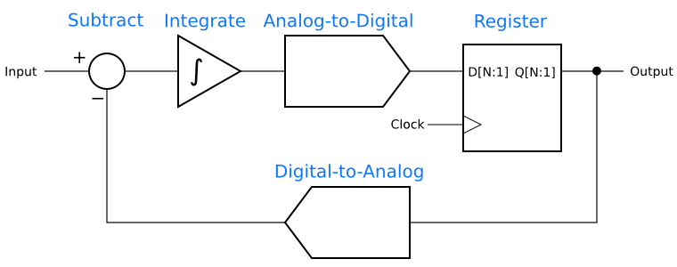
Abstract first-order delta-sigma modulator

Continue reading “How Delta Sigma Works, part 1: Introducing the Delta Sigma Modulator”
Farewell, Digi-Key catalog

The May 2011 High Frequency Electronics arrived with the sad news that the most recent Digi-Key catalog is the last, replaced by the www.digikey.com web site.  Digi-Key are also cancelling their TechZone magazine.

I suppose it was inevitable. The warning signs were certainly there, as Digi-Key sent thinner and less frequent catalogs to hobbyists than to professionals, then cut back  to annual issues. Nevertheless, I will miss the giant catalog that has always had a prominent place in my office and home lab.

I received my first Digi-Key catalog in 1983. Back then, it was thin, only 32 or 64 pages long. They had a good optoelectronics section, which remains one of their strengths. The only US semiconductor manufacturer they carried was National Semiconductor, though they distributed several lines of Japanese semiconductors.  (At one point, I wondered if National was Japanese, too!) Continue reading “Farewell, Digi-Key catalog”

Smoke testing the A3PN250 FPGA board

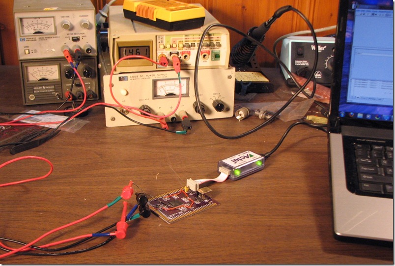
There comes a point in any project when one has to find out if it works, but first, there is the “smoke test”: Turn on the power and see if anything goes up in smoke. I smoke tested the A3PN250 FPGA breakout board this weekend, and it passed, or at least it failed to emit smoke. In any event, no smoke was emitted and the board survived. In fact, the board works. I talked to the board with a FlashPro4 programming pod and my rewired JTAG cable. The FPGA passed the pod’s signal-integrity check and identified itself correctly, so it is certainly alive.

The A3PN250 board on the bench


I follow a few rules of thumb when smoke testing. These aren’t things one learns in books, but instead from other engineers, so they are worth writing down and passing on. Continue reading “Smoke testing the A3PN250 FPGA board”

SiliconBlue ultra-low-power FPGAs

Some time ago, I wrote, “The Actel/Microsemi parts have one additional advantage: They have the best static power consumption in the industry.”  I was wrong.

Last month, a post on the geda-user mailing list alerted me to SiliconBlue Technologies and their line of ultra-low-power FPGAs. These FPGAs are RAM-based, like those of the big two FPGA manufacturers, Xlinix and Altera. Unlike the chips from the big guys, though, SiliconBlue’s parts are not power hogs. In fact, they are fully static and go down to microamps with a static clock.  With the Microsemi (Actel) FPGAs, one has to freeze the FPGA with the “Flash Freeze” feature to get down to that level, but it appears that the SiliconBlue units simply clock right down there.  If true, that would give them quite an edge in power-conscious design.

Making a direct comparison between the Actel/Microsemi Igloo line, their lowest-powered, and the SiliconBlue parts has to be done on a case-by-case basis. The clock rates, and in particular, how often the clocks can be stopped, matter a lot. There is also the external configuration EEPROM for the Silicon Blue parts, which will take power in simple designs, but can be powered down or perhaps eliminated in more sophisticated uses.

In any event, I will stick with the Microsemi ProASIC3 and Igloo line for now. I like the convenience of a flash-based architecture. The next time I’m designing for low power, though,  it will be time to give SiliconBlue a good look.

Updated 5/12/11: The date of the geda-user post was corrected.

Making progress on the A3PN250 FPGA breakout…

I’ve made lots of small steps on the A3PN250 FPGA breakout board the last two weeks.

Firstly, I built an JTAG adapter cable to work around a wiring error on the PCB. When I laid out the board, I accidentally numbered the pins on the JTAG connector DIP-style instead of ribbon cable style.  That meant that all the pins except for pin 1 were wired wrong. After thinking a bit about the options, which included scrapping the board and starting over, or skywiring in corrected wiring for the connector, I decided the cleanest solution was to make a custom JTAG cable that moved the pins around where they belong. I’d seen other cables built this way. I asked myself, “How hard could it be?” Continue reading “Making progress on the A3PN250 FPGA breakout…”