This post is part of a series on delta-sigma techniques: analog-to-digital and digital-to-analog converters, modulators, and more. A complete list of posts in the series are in the How Delta-Sigma Works tutorial page.
Today, let’s take another look at delta-sigma conversion. The first part of this series showed how a one-bit, first-order delta-sigma modulator creates a bitstream, the average value of which equals the input voltage. It turns out that how we find that average value makes a big difference in the performance of a delta-sigma analog-to-digital converter. In fact, if done right, not only does it improve performance, but it greatly simplifies the analog circuitry preceding the A-to-D. Let’s take a look at why this works!
Aliasing Explained
One phenomenon that happens with any analog-to-digital conversion is known as aliasing. A-to-D is inherently a sampling process, in which an analog signal that is continuous in time is converted to a digital signal that exists in discrete chunks, or samples. The rate at which those samples are taken is known as the sampling rate. The figure below shows three analog sine waves, in red, being sampled at the times marked with the blue vertical lines. The top sine wave has a frequency of 1 Hz, and it is being sampled at 7 Hz. (The seventh sample is not obvious, because it is zero and the left- hand or the right-hand edge of the graph. Which edge you choose is unimportant.)
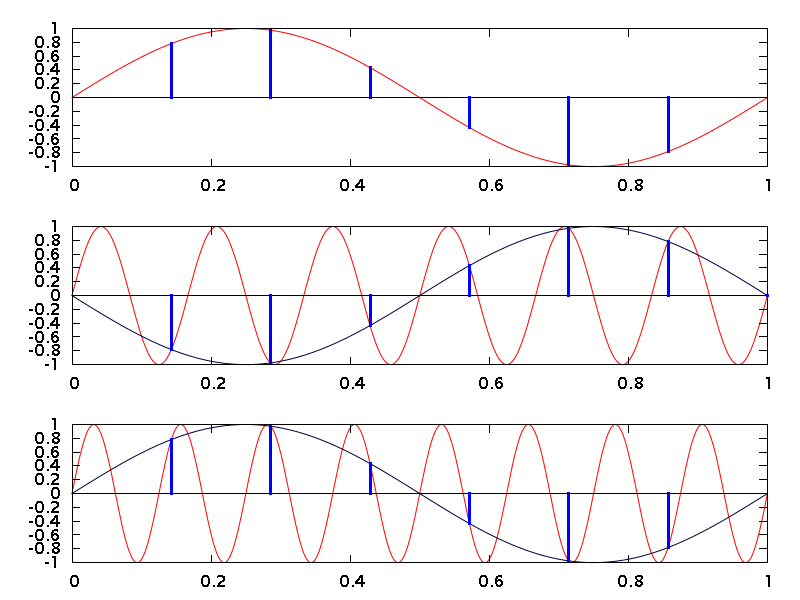
The second and third plots in the figure show aliasing in action. When any signal with a frequency above one-half the sampling rate is sampled, the signal is <i>aliased</i> down to a frequency between 0 Hz and one-half the sampling rate. The second line shows a 6 Hz sine wave in red, which is being sampled at 7 samples per second (sps). The blue lines show where the samples fall. Because 6 Hz is above 3.5 sps (one half of 7 sps), the sine wave will be aliased. As you can see, the blue samples are identical to those you see in the top trace, except that they have the opposite polarity. The dark blue trace connects them and shows that a 6 Hz sine wave is indistinguishable from a 1 Hz sine wave when both are sampled at 7 sps. That is aliasing in action.
The same process happens for any input frequency above one-half the sampling rate. The third plot in the figure, for example, shows an 8 Hz sine wave. Again, it is sampled at 7 Hz. This time the samples are identical to those in the top line. The sampled waveform (in dark blue once again) is indistinguishable from the sampled version of our original 1 Hz sine wave.
Aliasing is so important that one-half the sampling rate has become known as the “Nyquist frequency” for a system. You may see people refer to signals as being “above Nyquist” or “below Nyquist”. Aliasing happens in a repeated pattern as the frequency rises, and each repetiion of that pattern is called a “Nyquist zone”. All of this is in memory of Harry Nyquist (1889-1976), who with Claude Shannon discovered much of the mathematics behind sampling.
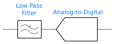
Because of aliasing, analog-to-digital converters are usually preceded by an anti-aliasing filter. This filter removes the frequency content outside of the desired Nyquist zone, so that noise and interfering signals do not alias into the passband of the ADC. Most often, a low-pass filter is used, so that the selected Nyquist zone runs from DC (0 Hz) to 1/2 the sampling frequency. There are some exotic RF applications in which a bandpass filter selects frequencies in a higher Nyquist zone, which the ADC then aliases down, but these are uncommon.
How Oversampling Makes Anti-Aliasing Easier
In order to get good accuracy, delta-sigma converters need to run at a much higher frequency than the input signal. The first part of this series introduced an idea for an ADC built from a delta-sigma modulator followed by a digital counter:
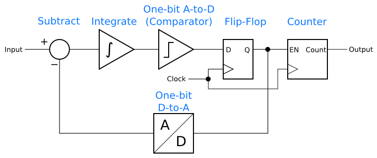
For this to work, the delta-sigma modulator has to <i>oversample</i>. In order to have the counter reflect the input signal accurately, there have to be many 1 and 0 bits in the modulator’s output for the counter to count. In other words, each sample from the counter’s output has to reflect many samples in the modulator. This is called oversampling.
The nice thing about oversampling is that the Nyquist frequency goes up with the sample rate, even when oversampling! The classic example of this happens in CD audio systems. CDs carry audio signals of up to 20 kHz, with a 44.1 ksps sample rate and a Nyquist frequency of 22.05 kHz. Furthermore, CD audio has a dynamic range of about 97 dB. In order to avoid aliasing signals back into the 0 Hz – 20 kHz audio band, the antialiasing filter at the input of a CD audio ADC needs to have a rolloff frequency (-3 dB) at 20 kHz, and should be down to -97 dB by 24.1 kHz. This is an impractical filter to design and build.
However, if an oversampled delta-sigma ADC is used, then the Nyquist frequency goes up to one-half the oversampled sample rate. A typical choice might be 64x oversampling, in which case the ADC will sample at 2.8224 MHz. Then the Nyquist frequency is 1.4112 MHz. The anti-aliasing filter still needs to have its -3 dB rolloff at 20 kHz, but it does not need to be -97 dB down until 2.82 MHz. That is a much easier filter to design. In fact, a 3-pole filter, easily and cheaply implemented with an op amp, is sufficient.
Moving Anti-Aliasing to the Digital Domain
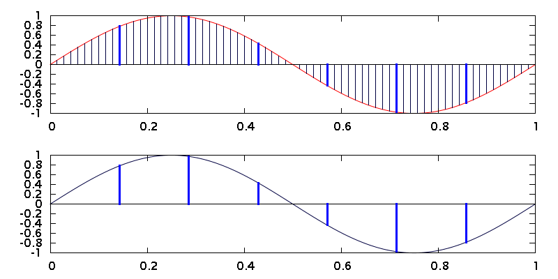
To go from 2.8 Msps to 44.1 ksps requires another round of sampling, this time in the digital domain. Remember the counter? The process of reading its count, then resetting it for another round of counting, is a form of sampling, and aliasing can result. The figure below shows an example. In this case, an 8 Hz sine wave is being sampled at 70 sps by an oversampling ADC. Then, that digital signal is being downsampled, by taking every tenth sample, to 7 sps. The result is that the 8 Hz input is aliased to 1 Hz, just as if it was sampled at 7 sps in the first place.

Just as in the analog domain, there are times when the aliasing resulting from downsampling can be useful, but often it is not. To prevent it, we need a low-pass filter, but this time the filter can be digital. In the CD-audio example, the filter needs to have the same rolloff characteristics as the challenging analog filter (-3 dB at 20 kHz, and -97 dB at 24.1 kHz). Doing that in a digital filter, though, is much easier than in analog. Digital arithmetic can produce a filter of arbitrarily good performance, without the precision components or careful tuning adjustments that might be required in analog. All it takes is throwing enough logic gates at the problem, and thanks to Moore’s Law, logic gates are cheap.
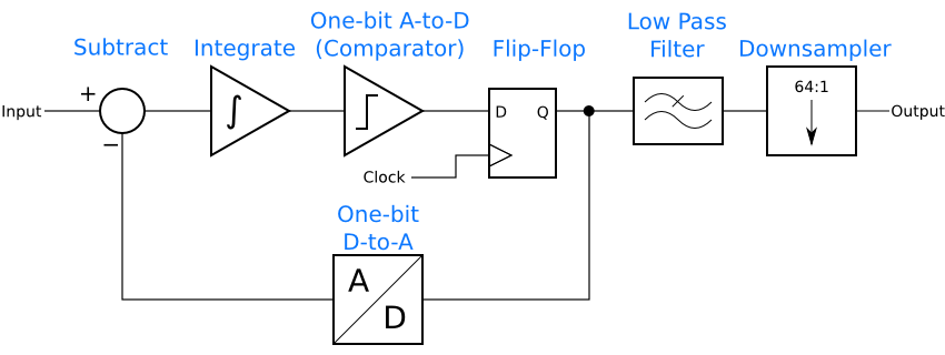
Since low-pass filters have an averaging effect, the filter will turn the bitstream of 1’s and 0’s into a series of multi-bit samples. The counter becomes unnecessary. Instead, it is enough to keep one sample from the low-pass filter’s output every so often, discarding the rest. The ADC now looks like this. (A simple anti-aliasing filter before the input is needed, but not shown.)
The figure below shows the principle. A 1 Hz sine wave is oversampled at 70 Hz in the top graph, then 9 out of every 10 samples are discarded, leaving only the highlighted ones. Those samples are plotted in the bottom graph. The result is identical to the sine wave samples in the first graph at the top of this article.
Technology similar to this, with some additional improvements to reduce the amount of math needed, makes it possible to put CD-quality ADCs in every desktop and laptop computer. Instead of an expensive analog filter, cheap digital gates on an IC provide most of the filtering, reducing the cost of the ADC to only a dollar or two.
Wrapping Up
In this article, we have come full circle to find out how delta-sigma techniques can make analog design easier. I’ve shown how aliasing happens and explained the need for anti-aliasing filters. Then we looked at the oversampling inherent to delta-sigma modulators, and how that permits a simpler analog antialiasing filter, at long as a digital low-pass filter is included after the modulator. This is just one of the reasons why delta-sigma principles are very cool. Coming up in this series: Simulating a delta-sigma modulator and an introduction to noise shaping.
Reference
Bourdopoulos, George I., Aristodemos Pnevmatikakis, Vassilis Anastassopoulos, and Theodore Deliyannis. Delta-Sigma Modulators: Modeling, Design and Applications. London: Imperial College Press, 2003
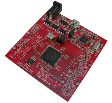 This week, I came across the Papilio One FPGA board. This intriguing board mounts a Xilinx Spartan 3E, in either the 250K or 500K gate flavor, along with power supplies and an on-board USB programmer. It’s inexpensive, at $50 for the 250K version and $70 for the 500K version. This would make a good pre-assembled alternative to the Microsemi SOC (née Actel) A3PN250 breakout board I am using.


