New job, New state, New call

Since my last post in November, my life is dramatically different. I changed jobs and industries, and I moved to the great state of Washington. Squeezed between Puget Sound and the Cascades, and watched over by Mounts Rainier and Baker, it is gorgeous here in the Seattle area. I will always be an Ohio boy, but Washington has been good so far. I even got a new callsign to go with my new address. I’m now KK7ZD.

Relocating is time-consuming beyond belief. The summer has been about unpacking, fix-it jobs, finding our way around our new city, and just a little bit of tourism. I’m waiting for the long, rainy nights of winter to set up my lab and resume work on the “Doan Brook” R2/T2 radio.

My new friends in the Western Washington DX Club are twisting my arm to participate in the Washington Salmon Run QSO party next weekend, though, so maybe I will find a bit of wire and my NorCal 40 and see if I can make some contacts with my new call.

I am considering a change in direction for the Skywired blog. My original vision was for a heavily technical focus on hardware projects, but changes in my life mean those kinds of big projects are less feasible. My career and hobby interests span the space where hardware and software meet, so it may make sense to shift focus slightly to include more software content. I’m not going to abandon electronic projects and in-depth tutorials, just cast a wider net for interesting content.

Some thoughts on the K5BCQ Si570 signal source

For the last few months, I’ve been working on building a radio from a pair of kits old enough to vote: KK7B’s R2 receiver and T2 transmitter. A complete transceiver built from these kits needs some other pieces, including a VFO (variable frequency oscillator). After looking around a bit, I picked an Si570 signal source kit from Kees Talen K5BCQ and John Fisher K5JHF.

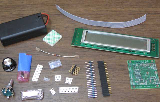
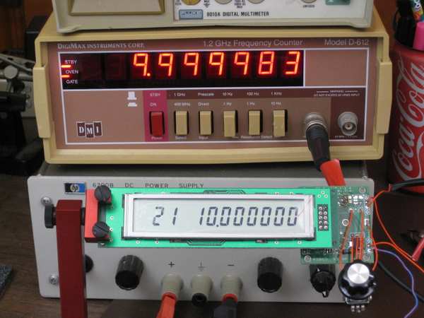
Si570 signal source and frequency counter, showing 17 Hz difference at 10 MHz

I’m not going to try to review the kit, because Jack Smith wrote the canonical review of it already. Instead, I will share some impressions of the kit.

First off, the PCB layout has not gotten better. There are some crazy things about it, including through-hole parts mounted on opposite sides of the board, such that one component prevents access to the terminals for another. The layout of the output circuit is also odd. In an effort to provide for many different output options, apparently while keeping trace lengths to a minimum, the output section is crowded and hard to navigate.

I had to do only a little debugging after assembly. The first problem was that the two pads at the ends of the Si570 were not well-soldered. Jack Smith ran into the same problem. My second problem was a little more subtle. I fired up the circuit and saw output at the right frequency, but 0.5 V in amplitude. I purchased the CMOS output option, so it should have been a 3.3 V square wave. Tracing out the circuit, I found that the signal was getting knocked down when it passed through a DC blocking capacitor. Oddly enough, I noticed that when my ‘scope probe pushed down on the right spot on the capacitor, the output jumped up to 3.3 V. I probably fractured the cap with the heat of soldering. I had changed my mind about capacitive coupling anyway, so I replaced the cap with a 0 ohm resistor and now I get the output I expect.

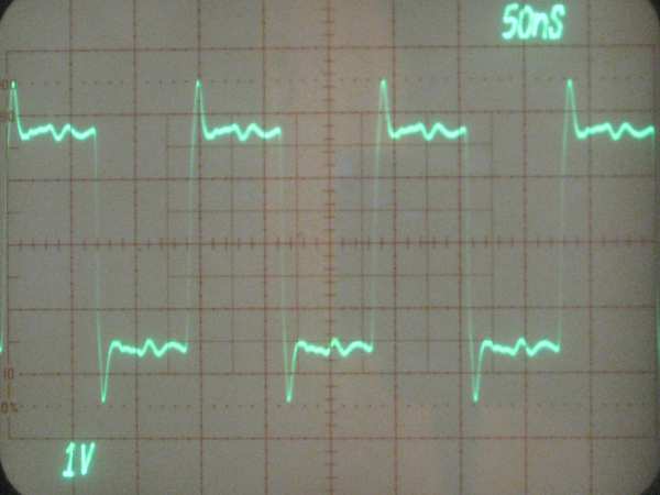
Waveform from the Si570 VFO

The ‘scope shot shows the output, which is a reasonably clean 3.3 V CMOS signal. There is almost a volt of overshoot on the transitions, which is a little concerning, but I am not too worried about it at this point. The CMOS edges are fast, making overshoot understandable, and the size of the overshoot is likely to change as the VFO is integrated into the radio. I will worry about it later.

All in all, I have to say that the board works a treat. It is awesome to see 1 Hz tuning resolution and crystal oscillator stability coming out of a tiny 8-pin surface-mount part. I measured the frequency as being off by about 14 to 17 Hz at 10 MHz, which works out to about 1.7 ppm. Drift is confined to that 3 Hz range, at least when sitting on my basement workbench. The board does have a provision to calibrate out the frequency error, which I have not used yet. This much error really doesn’t matter.

The microcontroller firmware with the kit works well. The user interface is slightly unusual, with a decimal point used as an input cursor, but it works fine in practice. I do wish there was a way to configure band limits. The board has provisions for band selection, with up to eight bands possible. However, regardless of the band selection, the device will tune over its entire range. In a multi-band radio that is a poor idea, because it would be too easy to transmit at the wrong frequency and damage the final amplifier. With hundreds of on-board memories (100 per band, minus 20 reserved for setup), it would be nice if a few configuration memories were used to choose tuning limits for each band.

Over all I am happy with the board. It will serve just fine as my VFO.

Working slowly on the R2/T2 radio

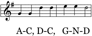
I was at my workbench when my son came downstairs to talk and hang out. A budding reader, he soon started singing the A-B-C song with the letters mixed up. It crossed my mind that this was odd, but I didn’t think much about it until I heard

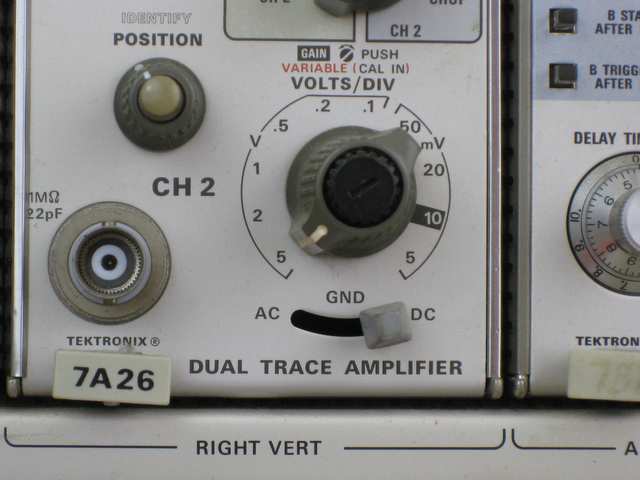
That rang a bell, and suddenly I realized he was singing my oscilloscope’s front panel. Music by Mother Goose, lyrics by Tektronix.

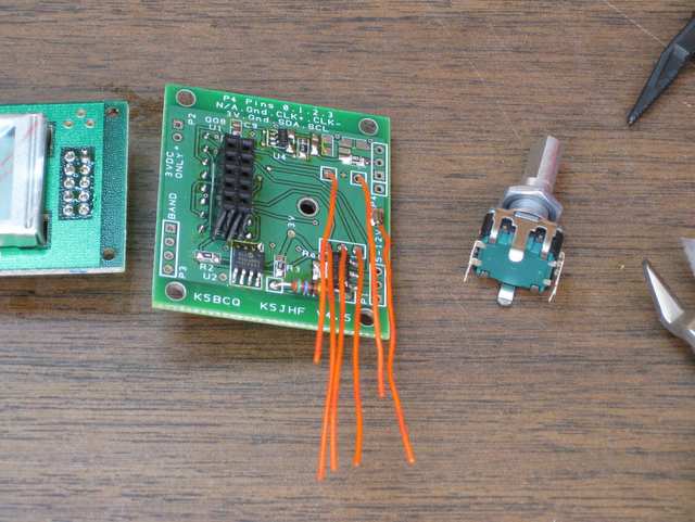
When he came downstairs, I was working on assembling the K5JHF/K5BCQ Si570 synthesizer kit. It turned out to be a bit fiddly, but it is a decent kit. That said, I would not lay out a PCB like this one. It has a number of vias in the middle of pads, and while that’s not a big problem for hand-soldering, I would avoid it in a PCB as a matter of good practice. You never know who might decide to use solder paste and reflow to assemble the board, and then those vias will be trouble.

Worse, though, is the positioning of the connector for the LCD. It is laid out smack in the middle of the footprint for the microcontroller, but on the opposite side of the board. If you look at the big black socket in the picture above, you will see the back side of the microcontroller’s pins poking through the board on either side of it. This positioning means one has to solder the header on one side of the board, then insert the micro on top of the pins one just soldered, flip over the board and solder the micro’s pins next to the header. The header pins are non-serviceable once the microcontroller is installed, and the microcontroller won’t be easy to get out, either. DIP desoldering tools won’t fit with the header in the way. I’m not sure why the board is laid out this way, except that it makes the board a little smaller. Maybe that was the only concern.

At this point, it’s fully assembled except for the encoder/switch, which is about half wired. What am I doing blogging? I could be soldering!

An Si570 VFO for the R2/T2 transceiver project

I’m continuing to work on my R2/T2 transceiver project as time allows. My goal is to get on the air before the sunspot cycle peak passes. That gives me a little time yet, but at the rate I get things built around here, it’s going to be a close race.

Even when building a radio from kits, as I am here, there are many decisions to be made. When I bought the KK7B R2 and T2 kits, I had no thoughts about what to use for a local oscillator. Technology has advanced mightily since then, and now I have the option of an Si570 frequency synthesizer. This little chip provides a precise, low-noise  digital clock at programmable frequencies between 3.5 MHz and 1.4 GHz, depending on the variant one buys.

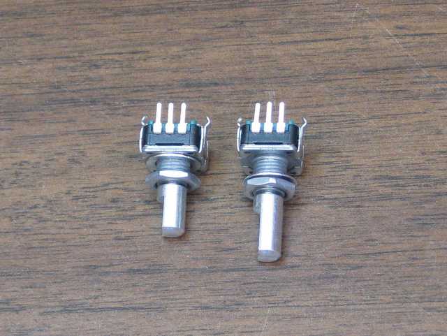
After looking around a bit, I picked John Fisher K5JHF and Kees Talen K5BCQ’s SI570 controller/frequency generator kit. Once it arrived, I had trouble figuring out how to fit it into my case. This case has a 0.125″ thick aluminum front panel. The threaded bushing on the kit’s encoder/switch was not long enough for this thick panel and a mounting nut, let alone a washer. There were also some mechanical things I didn’t like about the circuit board. I thought a bit about designing a new board for the parts from the kit, but I decided I could fix the worst of the problems with a new encoder. A little browsing at Mouser turned up an extremely similar model that had the longer bushing I needed. It even has the same footprint.

I’m a little stumped by how similar they are. The Mouser one (on the right) is from Bourns, but looking over the data sheet, I couldn’t find a model with a bushing and shaft length matching the one from the kit. The body of both units is essentially identical. Hopefully they are electrically close enough, too. I had to guess at how many pulses per rotation it should have.

I’m still chewing on another mechanical question. The kit is designed to have the PCB soldered to one end of the LCD, with the encoder mounted off the PCB, on the right of the LCD. I want to have the tuning knob centered below the LCD, so the PCB is going to have to stay with either the LCB or the encoder, and the other will have to be connected with wires. My initial thought was to mount the encoder on the PCB and wire the LCD remotely, but I’m beginning to favor mounting the PCB on the LCD and running wires to the encoder. The connection between the PCB and LCD will involve high-frequency digital signals, while the connection to the encoder is analog switch closures that have less potential for RF interference. It would be better to have the LCD signals cover a shorter distance so they radiate less.

On top of that, putting the PCB and the LCD together will make it easier to surround them with a shield.

All this rambling aside, yes, I’m making slow progress on the R2/T2 rig. When I’m working on a project, sometimes I spend a lot of time doing and other times I spend my time thinking. I’m a little out of my element with the mechanical design of the radio, so lately I’ve been planning the design carefully.

Going Forth, or maybe not.

Over the years, I keep coming back to the Forth programming language. I admire its lean design and very efficient use of resources, but oh, is it ever quirky. My most recent return was motivated by James Bowman’s J1 Forth CPU, a small but blazingly fast FPGA-based processor.

My ambivalence with Forth started back in the 1980’s, when an engineer named Tom Harsch mentored a very young me in digital electronics and computer architecture. Tom is an all-around engineer, versed in both hardware and software. He had a fondness for Forth, and he introduced it to me. Or perhaps I should say

ME FORTH TOM INTRODUCED

You see, the very first quirk one runs into when encountering Forth is its use of postfix notation to represent operations. While mainstream languages like BASIC and C would have syntax resembling this,

print 2 + 3

Or this,

printf(“%d\n”, 2 + 3);

Forth, in common with German, likes its verbs last. Here’s the Forth version:

2 3 + .

Don’t overlook that period, “.”, at the end. In Forth, that does not end a sentence; it is the command for printing a number.

Postfix notation is intellectually appealing, for several reasons. In postfix, every operation can be expressed with the same basic syntax, so there is no longer a need to distinguish between infix operators (+, -, *, etc.), unary prefix operators (like negation, -), and function calls. They all fit the same basic syntactic framework. Another advantage is that it maps very simply onto a stack-based processor model, which in turn can be implemented reasonably efficiently on many traditional CPUs or which really flies on dedicated hardware.

Forth uses postfix notation to permit the implementation of a simple compiler, which is usually built right into the run-time environment. The simplicity of the compiler results in further bizarre constructs, like the IF…ELSE…THEN statement. Not only are “ELSE” and “THEN” ordered backwards from pretty much every other language in the world, thanks to postfix notation, the “THEN” keyword comes after the code for the ELSE:

( condition ) IF ( then-actions ) ELSE ( else-actions ) THEN

On the bright side, this did give rise to a classic bumper sticker from the Forth Interest Group:

FORTH LOVE IF HONK THEN

Defining a function is straightforward, if you don’t mind punctuation:

: 2times 2 * ;

The colon (:) command defines a new “word” for the language. The next text, “2times”, is the name of the new word. That is followed by the instructions for the word and a semicolon (;) that ends the definition.

So what does this new word do? It multiplies whatever number came before it by 2. “5 2times .” is equivalent to “5 2 * .” and prints the number 10.

This syntax is admirably compact and naturally lends itself to a functional style. On the other hand, what is the name of the word doing after the colon?  In a postfix language, I would expect to quote the name and the function body, then use the defining word. Something like this:

‘2times (2 *) :

Flip that around and add a “lambda” and it starts to look like LISP, but that’s a subject for another time. In Forth, this kind of quirkiness, where everything is postfix except for the parts that aren’t, is standard. It keeps Forth’s compiler simple, but at a cost in elegance.

Syntactic quirkiness aside, Forth has a  few things going for it. First, it makes extremely efficient use of machine resources. A reasonable Forth environment can fit in 4K of RAM and include a compiler, an interpreter, and room for a small application. A full-featured environment is larger, but still takes less resources than equivalent functionality in other languages. Forth is generally fairly speedy, too.

Forth is extremely versatile. The compiler is implemented in an extensible way. You can define Forth words that alter how the compiler works, giving another way to work at higher levels of abstraction.

The philosophy behind Forth encourages programs to be organized in a hierarchy of small, simple functions. Each layer of functions builds a higher level of abstraction than the one that lies below it. I like this kind of well-factored programming, and it would be nice to work in a language that encourages it.

That brings me to the J1 Forth CPU. This compact Verilog core is a work of brilliance, particularly in the way it uses the FPGA’s dual-port RAM in a carefully designed data path to achieve a high instruction rate. The instruction set architecture is pretty much pure Forth, and the implementation was written to be fast. James Bowman’s paper on the J1 (pdf) is well worth a read, and so is the Verilog source code.

Ever since I read the J1 paper, I’ve been itching to find a use for it. (Yes, I know, that’s a solution in search of a problem…) My oft-delayed R2/T2 transceiver project offered a chance. As I thought about what to put on the front panel, my mind strayed to thoughts of touch-panel LCDs. Wouldn’t it be nice to be able to defer most of the user interface decisions to software? It’s much easier to move a button on a screen than to un-drill a hole. eBay has a number of nice touch panels that would fit my chosen case perfectly.

Besides, I’ve been getting in a bit of a rut lately. Though there was a time when I learned every language I could find, lately I’ve been using C almost all the time. How better to shake things up than by implementing a touch-screen user interface in Forth?  My favorite way to learn a new language is to dive into a major project. In fact, I learned C by writing a text editor. Next I learned C++ by writing two text editors. Then I learned Tcl by writing a text editor, and Prolog by writing tax software. (Go figure.)

Eventually I came to my senses. First off, I’m so busy these days that I’m finding it hard to spend any time on the R2/T2, let alone write graphics software for it. A more serious problem, though, is that the Actel FPGA I have handy has only 6K of RAM and limited capability for ROM or flash. To do the graphical user interface, I would want fonts in two sizes, and the J1 on this FPGA would not be able to store even one. I was brainstorming ways to extend the J1’s address space into off-FPGA storage when I had my Arduino epiphany. It does not make sense to spend time engineering complex font storage when a cheap, off-the-shelf processor has 32K of flash and the gcc C compiler at the ready.

Even with the Arduino standing by, I can’t get avoid being busy. No, the R2/T2 will have to make do with switches and knobs. Maybe in the future I can replace them with a touchscreen.

That settled, only one problem remains: I no longer have a problem for the J1 and Forth to solve.

Oh, well…

Updated 1/18/13 to correct the IF…ELSE…THEN syntax.
Rethinking Arduino: A review

I’ll admit it, I was wrong. I’m an engineer by profession, and one for whom designing a microcontroller-based PC board is old hat. I used to look down my nose at Arduino. Its populist appeal and simplified programming language made it a toy in my eyes. I have worked with other boards with similar goals of broad appeal that were poorly designed, with compromises that made the boards unusuable or that overstressed components, making them unreliable. Above all though, “real” engineers design boards for microcontrollers, and they program the microcontrollers using JTAG connections and arcane syntax — or so I thought.

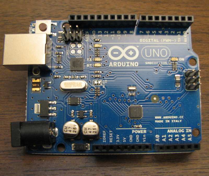
Arduino Uno circuit board

Then a few weeks ago, I was given an Arduino. My perspective has shifted. Arduinos may be populist, they may be the Radio Shack Engineer’s Notebook of the microcontroller world, but they’re also well-designed development boards worthy of any engineer’s attention.

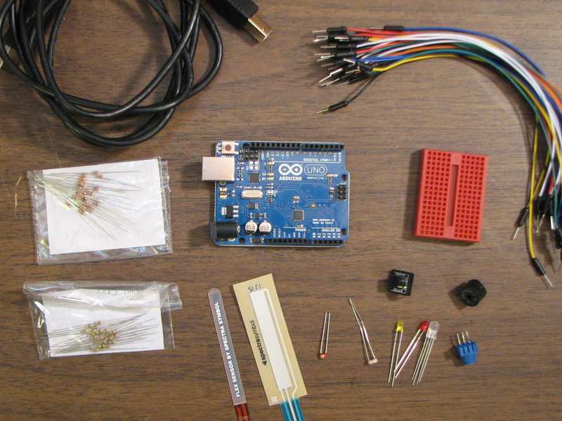
My Arduino came as part of a Sparkfun starter kit, which includes a breadboard, hookup wires, an RGB LED, packs of 1K and 10K resistors, and some fun sensors to play with, including a touch-sensitive resistor and a bend sensor. It amounts to a microcontroller-based building set, and would particularly appeal to anyone who wants to experiment with microcontrollers without having a specific project in mind. Though my son and daughter will be too young for the kit for a few more years, it caught my eye as exactly the sort of thing I might give to one of them to help them learn about what goes on inside a computer.

Sparkfun Starter Kit contents

I set the accessories aside and focused on the Arduino, an Uno model in this kit. Arduino’s current foundation model, the Uno includes a Atmel Atmega328 microcontroller, on-board power supplies (5V and 3.3V), a USB serial interface, a general-purpose LED, and female sockets that break out the microcontroller pins.

The Atmel processor is surprisingly speedy. It has an 8-bit CPU running at 16 MHz, which was plenty of processing power for the things I was trying to do. Perhaps the biggest limitation of the processor is its 2K of RAM. The 32K of flash on-board is great, and conservative programming techniques can fit a surprising amount of functionality into 2K of RAM, but sometimes it’s easier and faster to use a controller with more RAM.

The USB serial interface was a surprise as well. It is implemented by a second, smaller Atmel CPU, programmed to operate as USB-to-serial interface chip akin to the popular FTDI FT232 family. According to Arduino’s creators, the Atmel CPU was less expensive than the FTDI equivalent. Beyond being an interface, the second CPU has a USB bootloader and an ICSP (in-circuit serial programming) header of its own, so it can be reprogrammed just like the Atmega328. The USB CPU is in a tiny QFN package, and most of its I/O lines are not brought out. Still, the ability to reprogram it opens up a lot of interesting possibilities.

Arduino’s native programming environment uses a simplified C-like language. Since I’m comfortable with standard C and prefer test-driven development, I followed Nick Christensen’s detailed instructions on how to set up an Arduino development environment with gcc, Unity, and CMock. The gcc compiler is an industry standard tool these days, and I like Unity and CMock for unit testing.

Then I found out I was a snob. The Arduino wasn’t a toy. As I dug into its schematic and capabilities, I found a well-designed little development board. It was designed with cost-reduction in mind, for sure, but without losing sight of giving access to the entire capabilities of the processor. One processor pin drives an LED, for instance, but that line is also brought out to a header, making it available for other uses. The analog input pins are brought out without analog buffering, so they are available for digital I/O. Even the serial interface pins used to download code over USB can be repurposed.

There are other low-cost development boards, some directly competing with Arduino and others aiming for a slightly different audience. Here Arduino’s advantage is its popularity. Between Radio Shack and Micro Center, I can buy an original or cloned Arduino at retail from at least four stores within three miles of my house. That is surely not true for the entire world, but Arduino and software-compatible clones are also readily available online.

For my last small project, when I needed a microcontroller, I picked an inexpensive MSP430F2011 because TI’s EZ430 USB stick (which was a freebie from TI) could serve as the programmer. Next time, there’s a good chance I will use a genuine Arduino, one of the clones, or maybe just use these development tools with a plain Atmega328.

Yep, Arduino is worth a look, even for those used to the traditional “professional” world of microcontroller design.

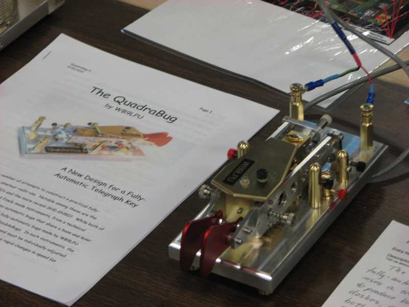
FDIM 2012: WB9LPU’s QuadraBug fully automatic key

This year’s Four Days in May at the Dayton Hamvention was full of sights to see. One amazing little piece of amateur engineering was Rich Meiss, WB9LPU’s “QuadraBug”, a mechanical key in the spirit of the Vibroplex Bug, but with fully automatic keying of both dits and dahs. (A bug has automatic dits, but manual dahs.)

Tom Perrera has put together a nice overview of Rich’s keys, starting from simple straight keys and working up to novel automatic keys like this.

My mechanical skills are limited. I have a lot of respect for those who can imagine and construct fine machines like this.