FDIM 2012: AA2JZ’s 40m transceiver

At this year’s Dayton Hamvention, I attended the Four Days In May QRP event put on by QRP-ARCI. A number of projects were on display, including this transceiver.

Carl Herbert, AA2JZ designed and built this 40m transceiver, drawing on the NW8020 as a source of inspiration. It uses NE602 mixers and two PIC microcontrollers, and includes a keyer and a frequency counter.

I was impressed by Carl’s tidy Manhattan-style assembly technique, in which small pieces of copperclad board (PCB material) are glued down and used as points to which wires and component leads are soldered. Most impressive is that he used the same technique for the chips. Carl must have a lot of patience to be able to position the little “nibbles” of copperclad at 0.1″ spacing to take the IC leads.

How Delta-Sigma Works, part 3: The controls-system perspective

This post is part of a series on delta-sigma techniques: data converters, modulators, and more. A complete list of posts in the series are in the How Delta-Sigma Works tutorial page.

In the first installment of How Delta-Sigma Works, I presented the basic first-order delta-sigma converter loop. Now it is time to begin digging a little deeper and look at how the loop works. To do this, we will need the mathematical tools of closed-loop control systems. Even without the mathematics, thinking about a delta-sigma modulator as a closed-loop controller can bring insight into how it works.

In engineering, closed-loop control is often used to keep a system working at a setpoint despite environmental disturbances or variations in the system itself. A furnace thermostat is a simple closed-loop controller, turning on the heat when the temperature drops below a setpoint and turning it back off when the temperature is above. Another example is vehicle cruise control. Unlike a thermostat, which usually has a binary output (on/off), cruise control adjusts the engine fuel control to maintain a roughly constant speed. In my car, it does this by physically moving the gas pedal. The environmental variations cruise control can encounter include hills, the quality of the fuel, and headwinds or tailwinds. The closed-loop controller adjusts the gas pedal as needed to maintain constant speed despite these effects.

A simple closed-loop control system can be drawn as in the figure below. The reference input, r, is the command input to the controller. In the thermostat example, r is the setpoint temperature, while for cruise control, it is the set speed. The output, y, is the controlled value. This is not necessarily in the same units as the reference input r. For example, in the cruise control, y might be a direct measurement of speed, or it might be something else related, such as a cumulative count of revolutions of the vehicle’s wheels.
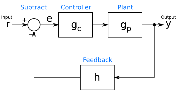
Basic closed-loop control system

In between the input r and the output y is the control loop. At the bottom of the loop, in its feedback path, a block h processes the output y into a form that is subtracted from the input r to create an error signal e. This error signal is an indication of how far the controller is from the desired operating point. The goal of a controller design is to keep e near, if not at, 0. The feedback block h can represent many different things. In the example of a cruise control system with the output y in units of distance, h might calculate speed by computing the derivative of y. In other systems, h might simply scale the value to convert its units. If y and r are already in the same units, such as in a thermostat example, h can pass through y unchanged (h = y).

Now that the error signal has been calculated, it is processed by the controller gc, the output of which goes to the “plant” being controlled. (To a controls engineer, anything being controlled, whether a car, a heating system, or a giant factory, is a plant.) The plant is represented by the box gp. The processing in the controller gc is easy to grasp. The controller calculates some function of its input in order to find the command it should give the plant.

What happens in this plant, gp, may be a little harder to imagine. The function gp is a mathematical model of the physics of the actual plant. It may be calculated from basic principles (a physicist’s delight!), or it may be an empirical model derived from the inputs and outputs of the actual plant. In any event, a reasonable guess at the function gp is necessary before one can design a closed-loop controller.

A delta-sigma modulator also has a closed loop, which suggests that perhaps insight can be gained by comparing it to a controller. The first-order delta-sigma analog-to-digital converter from the first installment, is shown again below.
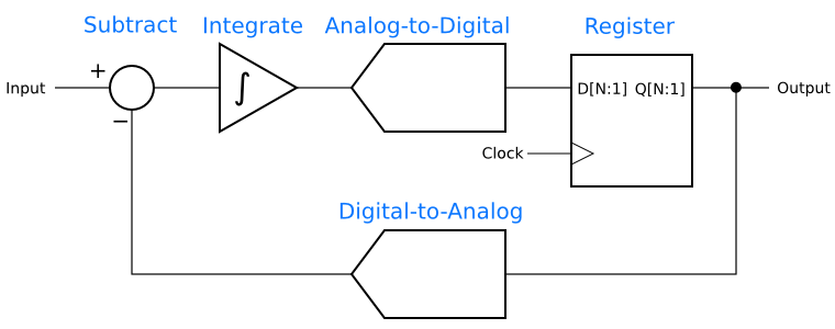
First-order delta-sigma modulator

The resemblance to a closed-loop controller is clear when one groups the blocks as in the next figure. The subtractor has the same function in both diagrams, comparing the input to the output. The integrator functions as the controller, gc, and the analog-to-digital convertor and its register are the plant, gp, being controlled. The digital-to-analog converter is the feedback path, h.
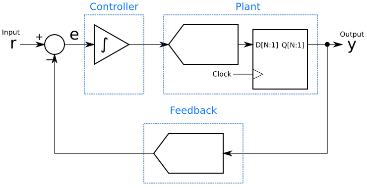
Grouping the delta-sigma elements by analogy to the closed-loop controller

This grouping gives immediate insight into how the delta-sigma modulator does its magic: It is a linear controller for an analog-to-digital converter, which is the plant. The controller is always trying to drive that plant’s output as close as possible to the setpoint, and does so by adding up (integrating) the error signal. Also, since the integrator is adding up the history of the error signal, it can be seen that although the output at any given moment may not equal the input, the long-term average will be equal. That integrator will try to keep the long-term average of the error, e, equal to 0.

There are many controllers that can control a given plant. PID (proportional-integral-derivative) controllers are simple and very popular, while more sophisticated controllers can be designed using other techniques. If a delta-sigma modulator is a control loop, it is reasonable to ask if controllers other than an single integrator will result in a better-performing modulator. In fact, other control functions can be used in delta-sigma modulators and can give lower noise or more desirable characteristics in the frequency domain.

Finally, one should not get too carried away with a linear control model. Analog-to-digital and digital-to-analog converters are inherently non-linear, while the mathematics of control theory primarily deals with linear systems. Assuming linear behavior will get us a long way towards understanding delta-sigma techniques, but it is important not to take the analogy too far.

Next in this series: Noise shaping, the frequency-domain secret behind delta-sigma data converters.
FDIM 2012: A field strength meter built onto a Harbor Freight DMM

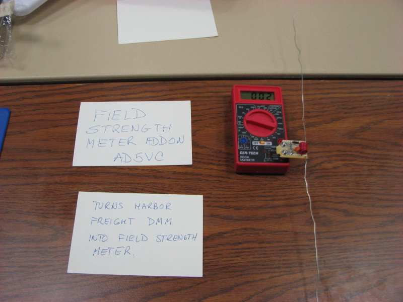
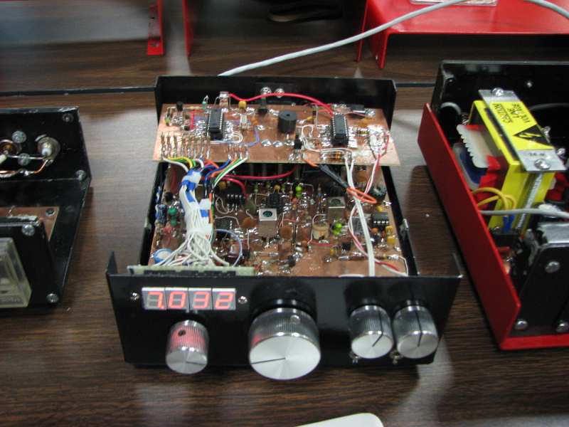
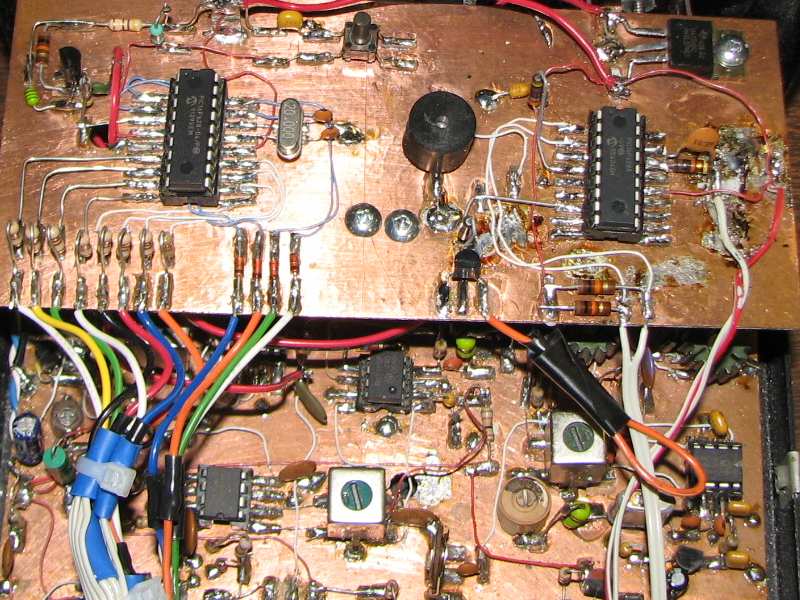
Continuing the series on neat projects I saw at the Four Days In May, here is a litle field strength meter built onto the side of a cheap Harbor Freight DMM by Dana Browne AD5VC.

ADC5VC field strength meter

Dana’s inspiration for the little field strength meter came when he was teaching a radio class to college students and wanted to show them the pattern of a Yagi-Uda antenna. He explained that cheap digital multimeters like this Harbor Freight model were readily available in the physics lab, so he built the field-strength circuit and  a little plug-in adapter using the DMM as the readout.

Though I don’t see much need for a field-strength meter in my shack, I admire Dana’s inventiveness in coming up with a solution that is cheap, convenient, and inexpensive.

An enclosure for the R2/T2 transceiver

After months of organizing parts, I have finally gotten back to the R2/T2 transceiver project. Don’t get me wrong, the cleaning and sorting is not done, but I felt the urge to do something a bit more… constructive.

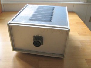
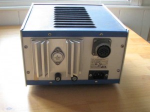
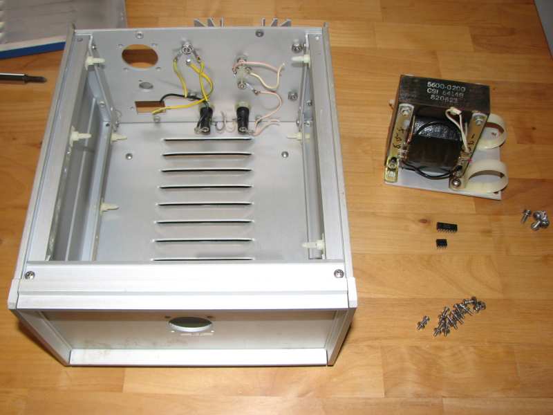
While cleaning, I found a box of old electronics junk that had promising cases. Electronics enclosures are expensive. Salvage can be a good way to keep the cost down. I don’t know what this thing once was, but there are military-style circular connectors on the front and back, two fuse holders, a power inlet, and no visible controls.


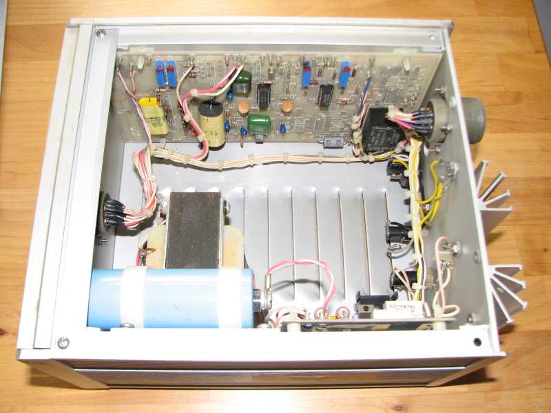
Opening it up, I found this:

There’s a lot of empty space in there! It looks like it was some kind of power supply. Next to the weighty transformer and big blue filter cap, a circuit board carried 7805 and 7806 regulators, several current-sense resistors and an LM324 quad op amp. It also had a power transistor on board and connected to the big TO-3 transistor on the heat sink in the back.

The board on the other side had a couple of high-voltage film capacitors, some ten-turn pots with their positions set with nail polish, two LM324’s and one RCA 4151 voltage-to-frequency/frequency-to-voltage converter. Down in the lower-right corner, it also held a solid-state relay. I’m a little more stumped about what this board was for. Maybe it was more power-supply logic, or maybe some kind of controller.

Tracing out the wiring harness revealed that 120VAC is run to the front connector, with only a fuse between the connector and the power cord. That could get exciting quickly to anyone not expecting it.

I pulled apart the whole thing, salvaging only the transformer, two ICs, and some fasteners. I tried to salvage all the ICs, but some were corroded into their sockets and could not be extracted without breaking pins. I have not had that happen before.

That’s the final product. I left the fuse holders, the heat sink, and a common ground point in place. They might be useful when this box becomes a transceiver. The front and back panel are 0.125″ aluminum and slide out after a few screws are removed. It will be easy to replace them with new panels for the radio.

The only fixed surfaces in this box on which to mount things are a pair of narrow rails on each of the side extrusions. The bottom is removeable and isn’t set up well to hold circuit boards. I will have to either add a false bottom or come up with a way to mounting the boards at right angles from the sides. Putting the boards flat on the sides, like the original residents of this box, won’t give me enough room, and because the boards are not sized to fit the walls, I would have to improvise some kind of mounting panel or angled standoffs to hold them anyway.

In any event, that problem is solvable. It’s a nice case for what I hope will be a nice radio.

FDIM 2012: The YADI micropower digital interface

Next in our tour of projects from the Four Days In May event at the Dayton Hamvention is an innovative radio-to-computer interface.

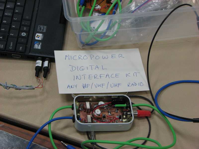
The YADI rig-to-computer interface prototype

The unique feature of YADI, Yet Another Digital Interface, is a micropower VOX circuit. This lets it sip power while waiting for a signal, where other interfaces are less battery-friendly. The secret is that the VOX amplifier is biased in “class E”, according to its designer, Dana Browne AD5VC. (It is possible he meant class C, since class E amplifiers are tuned and a VOX amp is broadband.)  That means that the amp uses no bias current when there is no signal. Its biasing also causes it to rectify the input, eliminating the need for an additional rectifier. The quiescent current is less than the self-discharge current of a 9V battery. In other words, the battery loses more energy sitting on a shelf than this interface needs to keep idle.

Dana, with Jim Giammanco N5IB, designed it with an eye towards emergency communications, particularly after hurricanes in their home state of Louisiana. It is designed to interface any radio and to any computer sound card, to support the many digital modes available today.

A kit version of the interface is being produced by the Baton Rouge Amateur Radio Club. The kit version was also on display at FDIM, but unfortunately, my photos of it did not come out. Suffice it to say that the kit includes a good-looking PCB, features easy through-hole assembly, and fits in a mint tin. The price is $35.

Unfortunately, I can’t find a link for the kit, other than some copies of the manual on a file sharing site. The BRARC web site is a vacant placeholder, and Google turns up no other leads. I hope this worthy kit becomes available soon and gets the publicity it deserves.

FDIM 2012: N8WE’s CW transceiver

A few weeks ago, I went to the Four Days In May event at the Dayton Hamvention, and brought back some pictures of the cool projects I saw.

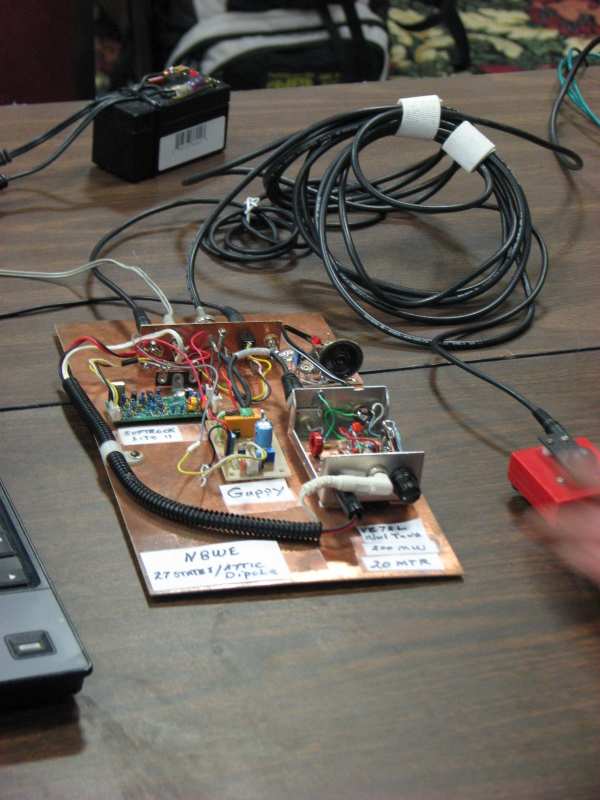
N8WE's 200 mW CW transceiver

Glenn Hazen, N8WE, brought his 20 meter transceiver project to show-and-tell night. The radio’s receiver uses a Softrock Lite II downconverter with a laptop running a software-defined-radio (SDR) application. The transmitter is a 200 mW Morse code transmitter. That’s the code key on the right.